
High-precision hydraulic numerical control punching machine

A CNC punch, high-precision technology, applied in the field of CNC punch, can solve the problems of lack of stability of workpiece, inability to fix workpiece, workpiece machining deviation, etc., to prevent offset, increase workload, and improve stability.

Inactive Publication Date: 2021-09-07
武汉天客行知科技有限公司
View PDF0 Cites 2 Cited by
  • Summary
  • Abstract
  • Description
  • Claims
  • Application Information

AI Technical Summary

Problems solved by technology

[0003] However, there are the following problems when installing and fixing the workpiece at present: 1. When the current numerical control punching machine is installing and fixing the workpiece, support pins that match the holes on the workpiece are mostly set on the workbench, and the support pins are used during work. Most of them are directly inserted into the holes of the workpiece, which only play a limiting role on the workpiece and cannot effectively fix the workpiece, so the workpiece lacks stability during processing;
[0004] 2. Usually, when the CNC punching machine replaces the workpiece, because the support pin cannot be adjusted according to the workpiece, it is necessary to replace the supporting pin that matches it, and then the support pin needs to be frequently disassembled and installed, thereby increasing the workload, and frequent disassembly, The installation is easy to make the support pin deviate, which will easily cause the machining deviation of the workpiece

Method used


Image

  • High-precision hydraulic numerical control punching machine
  • High-precision hydraulic numerical control punching machine
  • High-precision hydraulic numerical control punching machine

Examples


Embodiment Construction

[0031] The embodiments of the present invention will be described in detail below with reference to the accompanying drawings, but the present invention can be implemented in many different ways defined and covered by the claims.

[0032] Such as Figure 1 to Figure 7 A high-precision hydraulic numerical control punching machine shown includes a workbench 1, a discharge unit 2 and a punching knife 3. A discharge unit 2 is installed on the upper end of the workbench 1, and the punching knife 3 is arranged above the discharge unit 2. ,in:

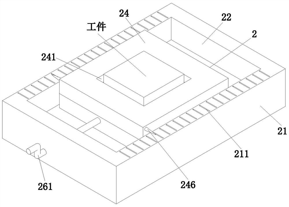
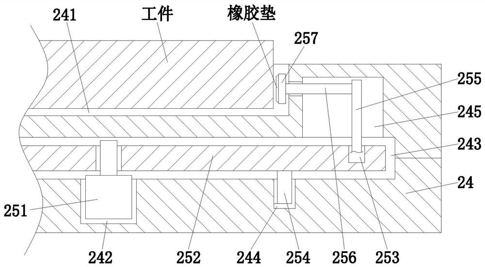
[0033] The discharging unit 2 includes a fixed seat 21, a sliding groove 22, a limit chute 23, a moving block 24, a locking assembly 25 and an adjusting assembly 26, wherein: the fixed seat 21 is installed on the upper end of the workbench 1, and the fixed The upper end of the seat 21 is symmetrical with the sliding groove 22 as the base point and is provided with scale marks 211 at equal intervals; One side is provided with a rotating hole...


PUM


Abstract

The invention provides a high-precision hydraulic numerical control punching machine, which comprises a workbench, a discharging unit and a blanking knife, wherein the discharging unit is mounted at the upper end of the workbench, and the blanking knife is arranged above the discharging unit. The invention can solve the following problems: firstly, when a workpiece is mounted and fixed by the existing numerical control punching machine, a support pin matched with a hole site on the workpiece is mostly arranged on a workbench, and the support pin is mostly directly inserted into the hole site of the workpiece during working, only plays a role in limiting the workpiece and cannot effectively fix the workpiece, so that the problem that the workpiece cannot be effectively fixed is solved, and therefore, the workpiece is lack of stability during processing; and secondly, when a workpiece is replaced by a general numerical control punching machine, the support pin cannot be adjusted according to the workpiece, so that the support pin matched with the workpiece needs to be replaced, and needs to be frequently disassembled and assembled, and thus, the workload is increased, the support pin is easy to deviate due to frequent disassembly and assembly, and the machining deviation of the workpiece is easy to cause.

Description

technical field [0001] The invention relates to the technical field of numerical control punching machines, in particular to a high-precision hydraulic numerical control punching machine. Background technique [0002] CNC punching machine is the abbreviation of digital control punching machine. It is an automatic high-precision hydraulic machine tool equipped with a program control system. The control system can logically process and decode programs with control codes or other symbolic instructions, so that The punching machine moves and processes the parts; the CNC punching machine has the following characteristics: high processing precision, stable processing quality; large processing area; when the processing parts are changed, generally only need to change the CNC program, which can save production preparation time; the punching machine itself has high precision, High rigidity and high productivity; the punching machine has a high degree of automation, which can reduce l...

Claims


Application Information

Patent Timeline
Patent Type & Authority Applications(China)
IPC IPC(8): B21D28/04
CPCB21D28/04
Inventor 黄雪巧
Owner 武汉天客行知科技有限公司
Learn More