
A non-isolated high-gain DC converter

A DC converter, high-gain technology, applied in the direction of converting DC power input to DC power output, high-efficiency power electronic conversion, instruments, etc., can solve the problem of large core size and on-state loss, system efficiency drop, and maximum gain. and other problems, to achieve the effect of reduced on-state loss, simple control and simple structure

Active Publication Date: 2022-05-20
JIANGSU UNIV
View PDF9 Cites 0 Cited by
  • Summary
  • Abstract
  • Description
  • Claims
  • Application Information

AI Technical Summary

Problems solved by technology

Similar to traditional Boost converters, under extreme duty cycle conditions, that is, D is close to 0.5, the system efficiency also drops sharply, so the actual maximum gain does not improve
In addition, in the above high-gain scheme, the average current of the input inductor is equal to the input current, so the core size and on-state loss are large

Method used


Image

  • A non-isolated high-gain DC converter
  • A non-isolated high-gain DC converter
  • A non-isolated high-gain DC converter

Examples


Embodiment Construction

[0025] The following will clearly and completely describe the technical solutions in the embodiments of the present application with reference to the accompanying drawings in the embodiments of the present application. Obviously, the described embodiments are only part of the embodiments of the present application, not all of them. Based on the embodiments in this application, all other embodiments obtained by persons of ordinary skill in the art without making creative efforts fall within the protection scope of the present invention.

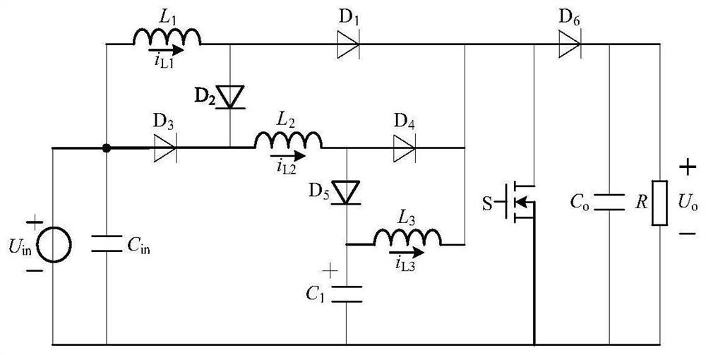
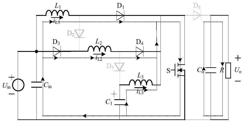
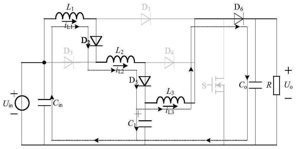
[0026] The invention provides a non-isolated high-gain DC converter, the circuit structure is as follows figure 1 shown. The non-isolated high-gain DC converter includes a DC power supply U in , Input filter capacitor C in , the first inductance L 1 , the second inductance L 2 , the third inductance L 3 , switch tube S, first diode D 1 , the second diode D 2 , the third diode D 3 , the fourth diode D 4 , the fifth diode D 5 , the six...


PUM


Abstract

The invention discloses a non-isolated high-gain DC converter. The positive pole of the DC power supply of the converter is connected to the positive pole of the input filter capacitor, one end of the first inductor, and the anode of the third diode; the other end of the first inductor is connected to the anode of the first diode and the anode of the second diode; The cathode of the tube is connected to one end of the second inductance and the cathode of the third diode; the other end of the second inductance is connected to the anode of the fourth diode and the anode of the fifth diode; the cathode of the fifth diode is connected to the anode of the first capacitor and the anode of the first capacitor One end of the three inductors is connected; the other end of the third inductor is connected to the cathode of the first diode, the cathode of the fourth diode, the anode of the sixth diode, and the drain of the switch tube; the cathode of the sixth diode is connected to the positive electrode of the output filter capacitor, One end of the DC load is connected; the other end of the DC load is connected to the negative pole of the output filter capacitor, the source of the switch tube, the negative pole of the first capacitor, the negative pole of the input filter capacitor, and the negative pole of the input power supply, with strong boosting capability and low current stress.

Description

technical field [0001] The invention belongs to the technical field of DC-DC step-up converters, in particular to a non-isolated high-gain DC converter. Background technique [0002] In recent years, high-gain DC-DC conversion technology has been widely used in uninterruptible power supply systems, renewable energy systems, fuel cells, and hybrid vehicles. However, in these applications, the output voltage of power modules such as photovoltaic cells, fuel cells, and storage batteries is low and varies in a wide range; for this reason, it is usually necessary to use a DC converter with a strong boost capability, and sometimes the voltage of the converter The gain even needs to reach more than a dozen to increase the output voltage to the voltage level required by the inverter. [0003] To this end, scholars from various countries have proposed various high-gain converter topologies, which can be roughly divided into two types: isolated and non-isolated. Compared with the fo...

Claims


Application Information

Patent Timeline
Patent Type & Authority Patents(China)
IPC IPC(8): H02M3/156
CPCH02M3/156Y02B70/10
Inventor 秦杨许兴
Owner JIANGSU UNIV
Learn More