
Matched type auxiliary automatic feeding and discharging conveying equipment for die stamping machine

A conveying equipment and supporting technology, applied in the field of stamping machinery, can solve problems such as hidden safety hazards, unfavorable workpiece quick and stable pick and place, increased manual work intensity, etc., to avoid impact deviation and damage, reduce manual labor output, place Easy-to-use effects

Active Publication Date: 2021-09-03
青岛瑞利杰金属有限公司
View PDF7 Cites 1 Cited by
  • Summary
  • Abstract
  • Description
  • Claims
  • Application Information

AI Technical Summary

Problems solved by technology

[0007] The purpose of the present invention is to provide a mold stamping machinery supporting automatic loading and unloading and conveying equipment, in order to solve the above-mentioned background technology, the existing mold stamping and loading and unloading conveying tools require more resources for manual use, and the labor intensity is increased. increase, which is not conducive to the rapid and stable pick-and-place of the workpiece, affects the processing efficiency of the workpiece and the safety of continuous processing, and there is a safety hazard in the human-assisted operation. The continuous accumulation of corners and scraps will affect the subsequent stamping stability and processing quality of the workpiece, and there will be problems such as sputtering caused by corner stamping.

Method used


Image

  • Matched type auxiliary automatic feeding and discharging conveying equipment for die stamping machine
  • Matched type auxiliary automatic feeding and discharging conveying equipment for die stamping machine
  • Matched type auxiliary automatic feeding and discharging conveying equipment for die stamping machine

Examples


Embodiment Construction

[0028] The following will clearly and completely describe the technical solutions in the embodiments of the present invention with reference to the accompanying drawings in the embodiments of the present invention. Obviously, the described embodiments are only some, not all, embodiments of the present invention. Based on the embodiments of the present invention, all other embodiments obtained by persons of ordinary skill in the art without making creative efforts belong to the protection scope of the present invention.

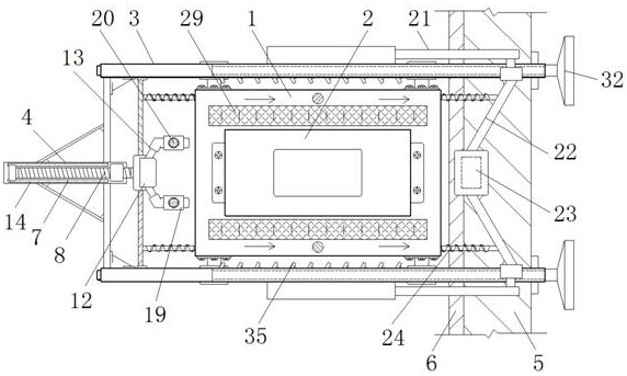
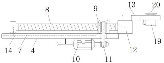
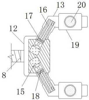
[0029] see Figure 1-7 , the present invention provides a technical solution: a mold stamping machinery matching auxiliary automatic loading and unloading conveying equipment, including a stamping table 1, a lower mold 2, an outer frame 3, a guide frame 4, a feeding conveyor belt 5, and a waste discharge belt 6 , chute 7, screw rod 8, threaded sleeve 9, motor 10, first chain belt assembly 11, connecting frame 12, discharge clip 13, conductive bottom plate 14, ...


PUM


Abstract

The invention discloses matched type auxiliary automatic feeding and discharging conveying equipment for a die stamping machine. The equipment comprises a stamping table, a motor, a hydraulic rod, a fixing frame and an air inlet cover. A lower die is installed on the top of the stamping table through a bolt, outer side frames are fixed to the left side and the right side of the stamping table correspondingly, and a guide frame is fixed between the left side ends of the outer side frames. Sliding grooves are formed in the two sides of the top of the guide frame, the motor is fixed to the bottom of the guide frame, a first chain belt assembly is arranged between the outer wall of an output shaft of the motor and the outer wall of a threaded sleeve in a sleeving mode, a connecting frame is fixed to the right end of a lead screw, and a discharging clamp is fixed to the center of the top of the connecting frame. The fixing frame is fixed to the end of an output shaft of the hydraulic rod. According to the matched type auxiliary automatic feeding and discharging conveying equipment for the die stamping machine, stamping workpieces can be efficiently and continuously taken and placed under the numerical control effect, manual labor output is reduced, and waste leftover materials can be continuously collected and discharged while the materials are taken and placed synchronously.

Description

technical field [0001] The invention relates to the related technical field of stamping machinery, in particular to an auxiliary automatic loading and unloading conveying equipment for mold stamping machinery. Background technique [0002] In the production and shaping of metal workpieces, in order to improve the stability and efficiency of the shaping, the pre-injection molded workpieces will be subjected to subsequent stamping and shaping processing, so that the local shape of the workpiece meets the needs of its production and processing. Before and after the stamping and shaping of the workpiece , it is necessary to manually take and place the workpiece repeatedly, and use artificial labor to realize the processing of the production workpiece, so as to prevent the workpiece from being repeatedly punched and other factors during the stamping process, resulting in damage to the production and processing of the workpiece. [0003] However, the existing mold stamping loading...

Claims


Application Information

Patent Timeline
IPC IPC(8): B21D22/02B21D37/10B21D43/12B21D45/04
CPCB21D22/02B21D37/10B21D43/12B21D45/04
Inventor 高伟
Owner 青岛瑞利杰金属有限公司
Learn More