Spliced mirror pose test system and method based on scanning galvanometer

A scanning galvanometer and testing system technology, applied in the field of active optics, can solve problems such as difficulty in adjusting the mirror position and attitude of the optical path system, increase the overall system error, reduce system stability, etc., so as to be beneficial to test control and reduce the overall error. , the effect of simple structure

Active Publication Date: 2021-08-31
HEFEI UNIV OF TECH
View PDF5 Cites 0 Cited by
  • Summary
  • Abstract
  • Description
  • Claims
  • Application Information

AI Technical Summary

Problems solved by technology

[0004] However, the splicing mirror technology used in active optical technology also has many problems, among which how to realize the adjustment of the relative pose between each mirror surface of the splicing mirror is always a prominent problem that needs to be solved in engineering
In the process of conducting traditional large-aperture active optical indoor experiments, due to the influence of the experimental space, the diameter of the splicing mirror and the size of the S-H sensor detection aperture, it is necessary to integrate the optical path system, and at the same time control the size of the spot incident on the surface of the splicing mirror to be large enough to Covering the full aperture for detection of wavefront phase information will introduce certain difficulties to the adjustment of the overall optical path system and the adjustment of the mirror pose. At the same time, the complex structure of the splicing mirror system will reduce the stability of the system and increase the overall system error. The corresponding staff will also have difficulties in the process of controlling the adjustment. Therefore, it is necessary to propose a more effective method for the pose test of the splicing mirror

Method used


Image

  • Spliced mirror pose test system and method based on scanning galvanometer
  • Spliced mirror pose test system and method based on scanning galvanometer
  • Spliced mirror pose test system and method based on scanning galvanometer

Examples


Embodiment 1

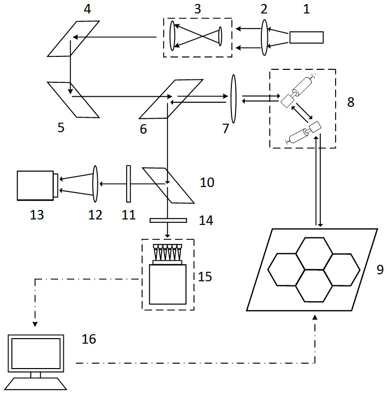
[0047] See figure 1 , a scanning galvanometer-based splicing mirror pose test system, the test system includes a transmitting unit, a receiving unit, a detection unit and a correction unit;

[0048] The launch unit includes,

[0049] The laser transmitter 1 is used to generate the coherent light source required in the pose test system, and the coherent light source is divergent light,

[0050] The first lens 2 is used to receive divergent light and refract the divergent light into parallel light,

[0051] The beam expander 3 is used to amplify the beam diameter of the parallel light in proportion to obtain the expanded beam,

[0052] The first reflector 4 and the second reflector 5 are used together to change the propagation direction of the beam expansion light, and are combined with the double diaphragm to collimate the beam expansion light to obtain collimated beam expansion light;

[0053] The receiving unit consists of,

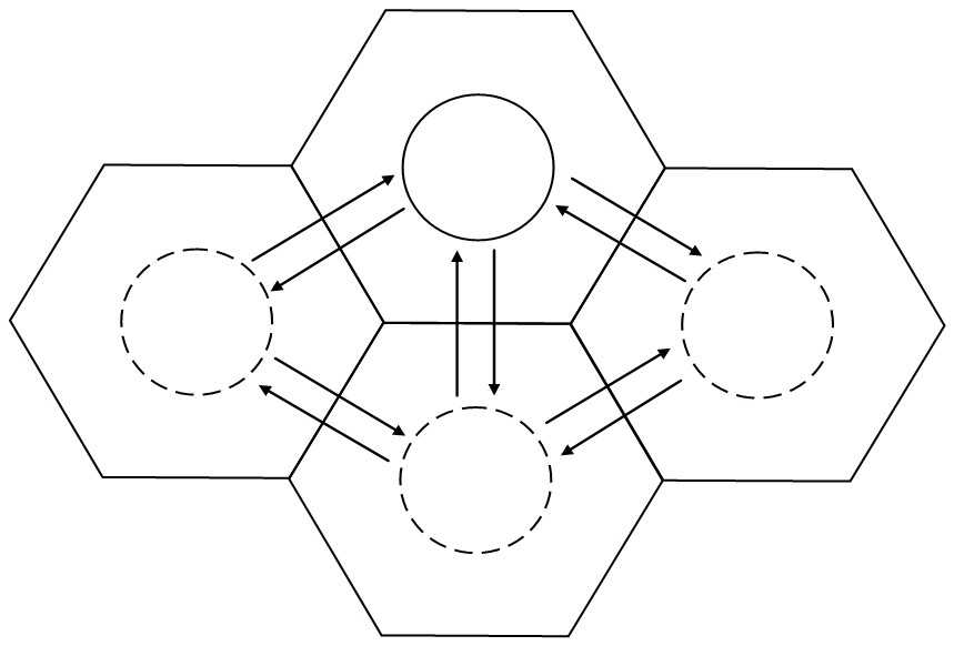
[0054] The splicing reflector 9 is spliced ​​b...

Embodiment 2

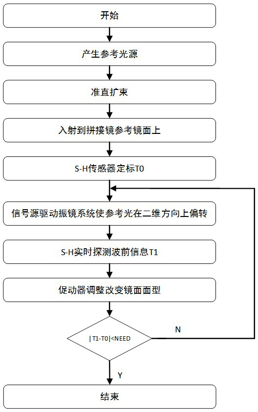
[0069] See image 3 , the flow chart of the test method of the above-mentioned splicing mirror pose test system,

[0070] The test method of the above-mentioned reflector space pose test system comprises the following steps:

[0071] Step 1): The emitting unit emits collimated beam expansion light,

[0072] Step 2): A splicing mirror of the receiving unit receives the collimated and expanded beam and returns according to the original path to obtain reflected light.

[0073] Step 3): The detection unit receives the reflected light of the splicing mirror to obtain the reference wavefront phase information, and stores the reference wavefront phase information,

[0074] Step 4): Based on the reference wavefront phase information, the correction unit uses the mode method in the wavefront restoration algorithm to calculate the value of the corresponding coefficient of the Zernike polynomial, and fine-tune the pose of the above-mentioned splicing mirror until the inclination and di...


PUM


Abstract

The invention belongs to the technical field of active optics, and particularly relates to a spliced mirror pose test system and method based on a scanning galvanometer. The system comprises a transmitting unit, a receiving unit, a detecting unit and a correcting unit. The testing system is simple in structure, high in integration and beneficial to equipment building and personnel testing. The whole system is stable, the adjusting efficiency is high, and system errors can be reduced to a great extent; the emitting unit emits collimated and beam-expanded light; a first beam splitter of the receiving unit receives the collimated and expanded light, a second lens diverges the collimated and expanded light, and a scanning galvanometer receives the collimated and expanded light and reflects the collimated and expanded light to a splicing mirror; a second beam splitter of the detection unit receives the reflected light and splits the reflected light, wherein one beam is transmitted to an S-H sensor, and the other beam is reflected to a CCD camera; the correction control unit receives the wavefront phase information and corrects the mirror surface type of each spliced mirror through algorithm feedback, and the test system completes the space pose test and correction of each spliced mirror of the reflector and meets the imaging quality requirement.

Description

technical field [0001] The invention belongs to the technical field of active optics, in particular to a scanning galvanometer-based splicing mirror pose testing system and method. Background technique [0002] For an optical telescope, the ability to gather light and angular resolution are the two most important parameters. According to Rayleigh's criterion, the larger the aperture of the telescope, the smaller the limit angular resolution and the stronger the resolving power. Therefore, in the process of telescope development, astronomers have always expected to obtain higher light-gathering capabilities and stronger angular resolution by continuously expanding the aperture of the telescope, so as to achieve high-resolution observation of farther and weaker targets in space. However, in the development process of large-aperture telescopes, optical errors will inevitably increase, and the cost of raw materials required will also increase. In the process of being put into ...

Claims


Application Information

Patent Timeline
IPC IPC(8): G01C21/00G01M11/00G01J9/00
CPCG01C21/00G01M11/00G01J9/00G01J2009/002
Inventor 夏豪杰袁梓阳宁书铭李哲余鑫丁思雨
Owner HEFEI UNIV OF TECH
Why Eureka
Try Eureka