Fiber tension adjusting process and equipment
A technology for adjusting equipment and fiber tension, applied in the textile field, can solve the problems of inability to form a protective layer on the surface of fiber filaments, cannot save manpower and material resources, and is not convenient to operate, so as to achieve the effects of saving process costs, strong practicability, and convenient operation
- Summary
- Abstract
- Description
- Claims
- Application Information
AI Technical Summary
Problems solved by technology
Method used
Image
Examples
Embodiment 1
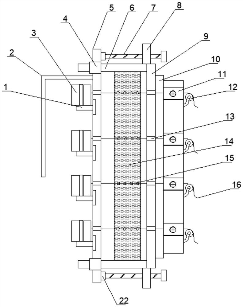
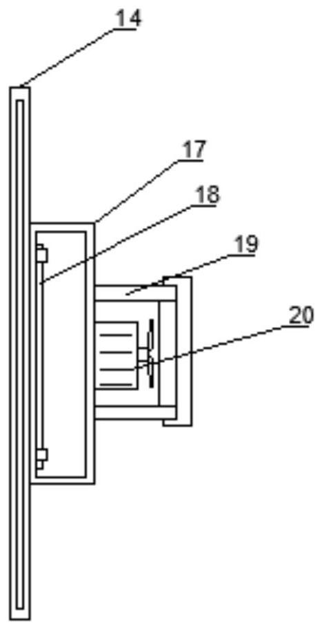
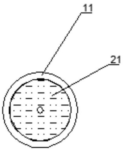
[0025] A fiber tension adjustment device, comprising a side plate 9 and a moving column 5, one side of the side plate 9 is welded with a stopper 10, one side of the stopper 10 is installed with a rubber sleeve 11 through a screw, and One end of the bottom of the rubber sleeve 11 is provided with a fixed pulley 12 through a fixed frame. The rubber sleeve 11 is provided with a sponge block 21. The top and bottom ends of the installation side plate 9 are welded with guide rods 6. The guide rods The both sides of 6 are welded with screw thread block 8, and one end of described guide rod 6 is provided with moving column 5, and the two ends of described moving column 5 are provided with guide sleeve 4, and guide rod 6 runs through guide sleeve 4, and described moving column 5. A protective cover 2 is welded on the top end of one end, and the lower end of the protective cover 2 is provided with a winding disc 3 through the drive motor 1. A hollow plate 14 is installed on one side of t...
Embodiment 2
[0038] A fiber tension adjustment device, comprising a side plate 9 and a moving column 5, one side of the side plate 9 is welded with a stopper 10, one side of the stopper 10 is installed with a rubber sleeve 11 through a screw, and One end of the bottom of the rubber sleeve 11 is provided with a fixed pulley 12 through a fixed frame. The rubber sleeve 11 is provided with a sponge block 21. The top and bottom ends of the installation side plate 9 are welded with guide rods 6. The guide rods The both sides of 6 are welded with screw thread block 8, and one end of described guide rod 6 is provided with moving column 5, and the two ends of described moving column 5 are provided with guide sleeve 4, and guide rod 6 runs through guide sleeve 4, and described moving column 5. A protective cover 2 is welded on the top end of one end, and the lower end of the protective cover 2 is provided with a winding disc 3 through the drive motor 1. A hollow plate 14 is installed on one side of t...
PUM
 Abstract
Description
Claims
Application Information
 - Generate Ideas
- Intellectual Property
- Life Sciences
- Materials
- Tech Scout
- Unparalleled Data Quality
- Higher Quality Content
- 60% Fewer Hallucinations
Browse by: Latest US Patents, China's latest patents, Technical Efficacy Thesaurus, Application Domain, Technology Topic, Popular Technical Reports.
© 2025 PatSnap. All rights reserved.Legal|Privacy policy|Modern Slavery Act Transparency Statement|Sitemap|About US| Contact US: help@patsnap.com


