Decorative wallboard structure and mounting method thereof
A panel structure and decorative wall technology, applied in the direction of walls, building components, building structures, etc., can solve the problems of environmental damage around the building, sewage splashing everywhere, etc., and achieve the effect of high cleaning efficiency
- Summary
- Abstract
- Description
- Claims
- Application Information
AI Technical Summary
Problems solved by technology
Method used
Image
Examples
Embodiment 1
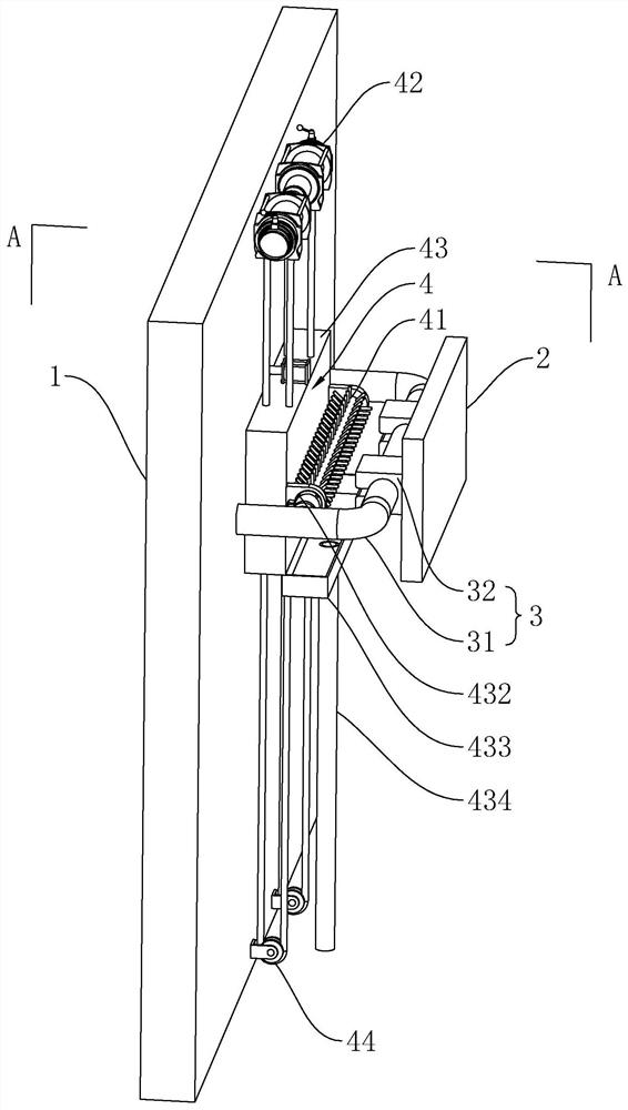
[0043] Such as figure 1 As shown, a decorative wallboard structure includes a wallboard 2 and a connecting piece 3 for connecting the wallboard 2 to the exterior wall 1. The connecting piece 3 includes a connecting rod 31 and a connecting block 32, and the connecting rod 31 extends along the horizontal direction. The two ends of the connecting rod 31 in the length direction are bent towards the direction close to the outer wall 1 for fixing with the outer wall 1, the connecting block 32 slides through the connecting rod 31, and the wall board 2 and the connecting block 32 are far away from the outer wall 1 fixed at one end.
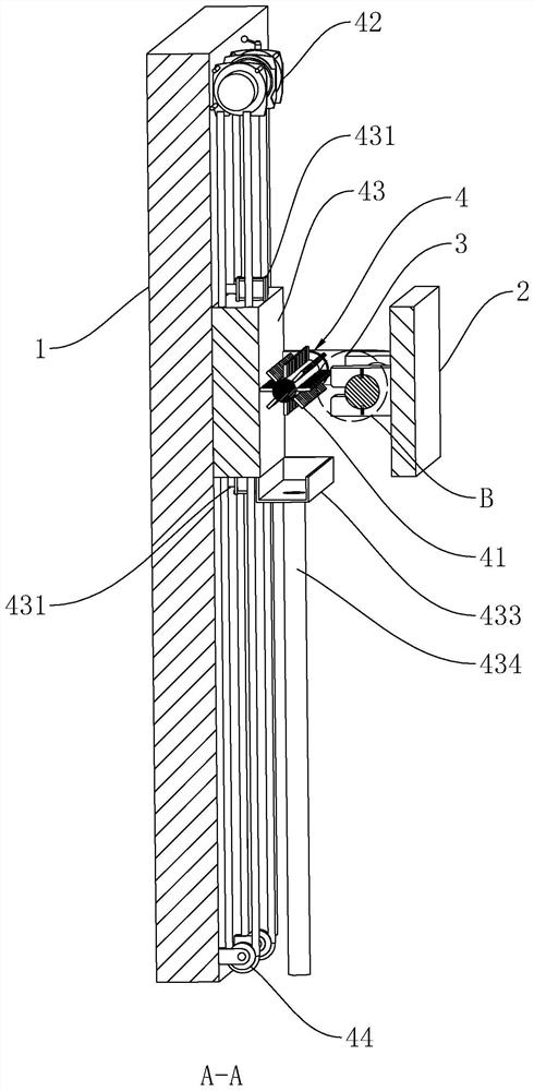
[0044] Such as figure 1 , 2 As shown, a gap is formed between the outer wall 1 and the connecting rod 31 for the wallboard 2 to turn axially around the connecting rod 31, so that the side of the wallboard 2 away from the outer wall 1 can be turned over 180° during cleaning.
[0045] A cleaning assembly 4 is installed between the outer wall 1 and the co...
Embodiment 2
[0052] Compared with the first embodiment, the difference is:
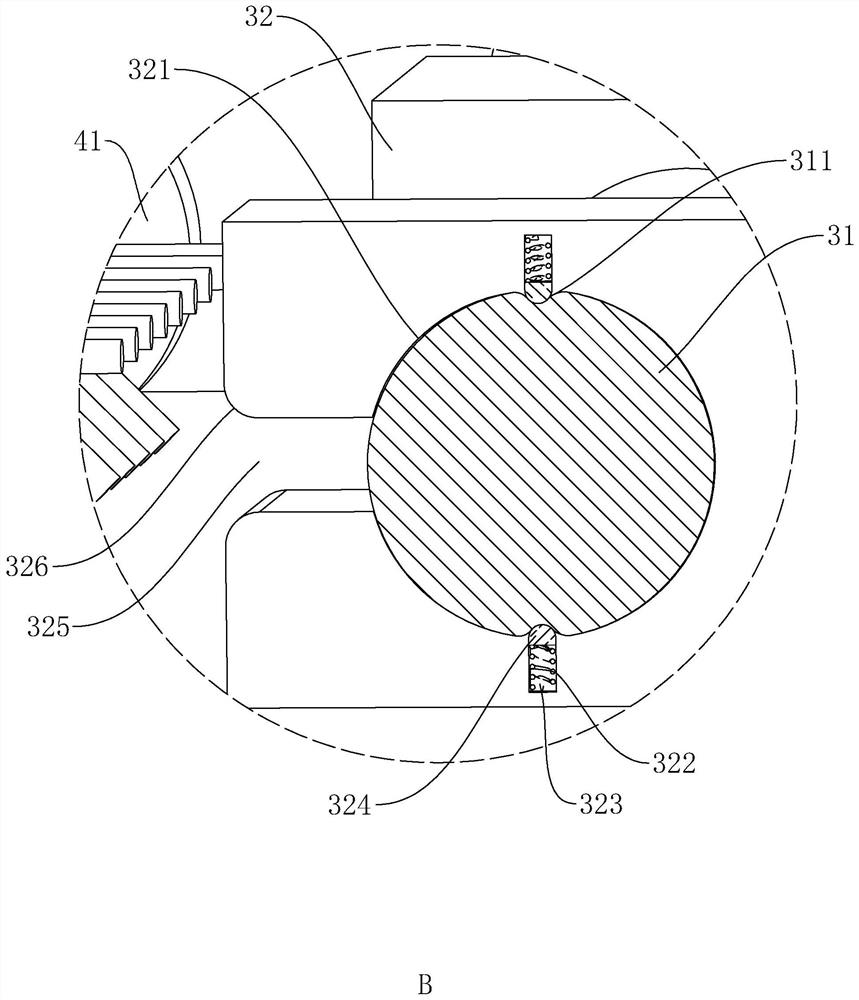
[0053] Such as figure 1 , 3 As shown, the connecting block 32 is provided with a connecting groove 321 along the length direction of the connecting rod 31, and the connecting rod 31 is penetrated in the connecting groove 321; a limiting groove 322 is provided in the connecting groove 321 along the vertical direction, and the limiting groove 322 is in the vertical direction. Both sides of the connecting groove 321 in the vertical direction are opened, and a compression spring 323 is installed in the limiting groove 322. One end of the compression spring 323 is fixed to the bottom of the limiting groove 322, and a snapping ball is provided for sliding in the limiting groove 322. 324, one end of the clamping ball 324 is fixed to the end of the compression spring 323 away from the groove bottom.
[0054] On the connecting rod 31, a snap-in groove 311 for snap-in ball 324 is provided at the position corresponding to ...
Embodiment 3
[0058] Used for construction to form the decorative wallboard structure described in Example 1:
[0059] Such as figure 1 As shown, in step one, the connecting rod 31 is pre-embedded,
[0060] During the construction of the building exterior wall 1, the connecting block 32 is slid to be inserted between the two ends of the connecting rod 31, and then the two ends of the connecting rod 31 are pre-embedded on the outer wall 1, so that the two ends of the connecting rod 31 Form a certain gap with the outer wall 1;
[0061] Step two, install the wall panel 2,
[0062] Just fix the end of the connecting block 32 away from the outer wall 1 to the wallboard 2 .
[0063] Before installing the wallboard 2, the connecting rod 31 is pre-embedded on the outer wall 1, and the connecting block 32 is slid to penetrate on the connecting rod 31 in advance, which can reduce the construction time when fixing the wallboard 2 and improve the installation efficiency.
PUM
 Abstract
Description
Claims
Application Information
 - R&D Engineer
- R&D Manager
- IP Professional
- Industry Leading Data Capabilities
- Powerful AI technology
- Patent DNA Extraction
Browse by: Latest US Patents, China's latest patents, Technical Efficacy Thesaurus, Application Domain, Technology Topic, Popular Technical Reports.
© 2024 PatSnap. All rights reserved.Legal|Privacy policy|Modern Slavery Act Transparency Statement|Sitemap|About US| Contact US: help@patsnap.com


