Surface grinding equipment for stud bolt processing

A stud bolt, grinding technology

Active Publication Date: 2021-10-12
烟台佑利技术有限公司
View PDF1 Cites 2 Cited by
  • Summary
  • Abstract
  • Description
  • Claims
  • Application Information

AI Technical Summary

Problems solved by technology

[0003] Patent No. CN112123156A discloses a bolt grinding and derusting equipment, including a base plate, the upper end of the base plate is provided with bolts, the bolts are fixed with threads, and the bolts are equipped with nuts. The upper side of the base plate is provided with an installation platform, the installation platform is provided with a turntable cavity, the rotation of the turntable cavity is provided with a linkage turntable, and the installation platform is fixed with a semicircular card slot, compared with the present invention , it cannot complete the processing operation of multiple sets of stud bolts at one time, and the work efficiency is low
[0004] The existing surface grinding equipment based on stud bolt processing has certain disadvantages in the process of use. The traditional surface grinding equipment can only grind a single stud bolt at a time, and the work efficiency is low, which makes it The grinding operation of multiple sets of stud bolts cannot be completed at one time; at the same time, the traditional surface grinding equipment does not have an auxiliary feeding structure. The bolts are loaded, which increases the operation steps in the preparatory operation; at the same time, the traditional surface grinding equipment does not have a waste cleaning structure, which increases the difficulty of the later cleaning and maintenance operations of the surface grinding equipment, which brings certain problems to the user. Adverse effects of

Method used


Image

  • Surface grinding equipment for stud bolt processing
  • Surface grinding equipment for stud bolt processing
  • Surface grinding equipment for stud bolt processing

Examples


Embodiment 1

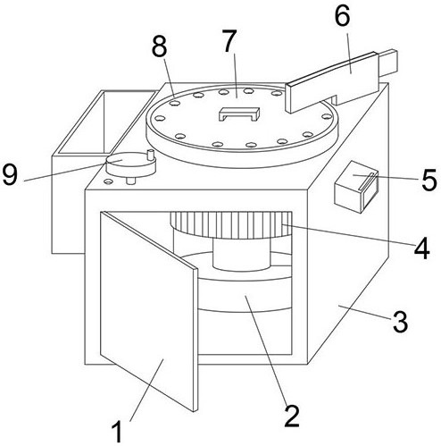
[0037] The upper annular distribution of the splicing chuck 7 has a plurality of round holes for mounting the double-head bolts, and the splicing chuck 7 and the rotary collar 8 are fixed by two sets of docking snaps 17, using the circle on the splicing chuck 7. The holes can be installed in one time, and the inserted double-bolts are passed through the side of the grinding disc 4 in the side of the grinding plate 4, and when the double bolt is polished, the grinding disc is driven when the bolt bolt is polished. 4 Rotate so that the grinding disc 4 can simultaneously complete the grinding operation of the multi-set double bolt.

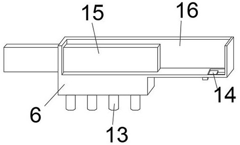
[0038] An end activity is attached to one end of the feed cassette 6, and the inner side of the feed cassette 6 is provided with a receiving groove 16, and the bottom position of the other end of the feed cassette 6 is provided with a tank. When the feed cassette 6 is used, the user passes Place a row of double-head bolts inside the receiving tank 16 of ...

Embodiment 2

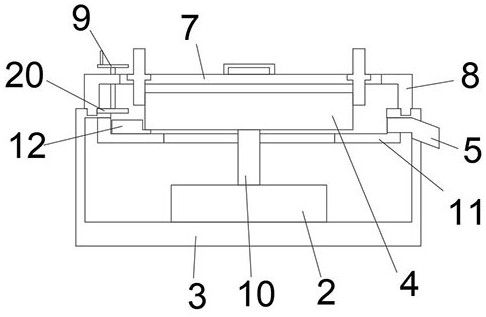
[0040] The bottom of the feed cassette 6 is provided with a fixed bolt 13, and the other end of the feed cassette 6 is located in the inside of the discharge slot. The push-pull buckle 14 is attached, and the user can adjust the size of the tank by pushing the push-pull buckle 14. The adjustable discharge slot can be used with a lower end of the rotating collar 8, and the rotary collar 8 and the first pick-up disk 18 are provided with an annular card slot between the lower ends of the rotating collar 8. The setting of the card slot can be mounted on the upper portion of the fixed base 3, and can drive the rotation jacket 8 using the first tootooth 8 to complete the rotation operation.

[0041] The inner active sleeve of the drive hand wheel 9 is attached to the positioning rod 21, and the lower portion of the driving hand wheel 9 is fixedly mounted, and the driving hand wheel 9 and the third tooth plate 20 are connected by the rotor, the third tooth disc 20 The side activity is at...

Embodiment 3

[0043] The inner side of the fixed base 3 is fixed to the lower surface of the grinding disc 4, and the outer surface of the fixed base 3 penetrates the tapered slag nozzle 5, which is generated when the double bolt grinding operation is operated. The metal dust will fall into the slagm 11, and the metal dust is collected by the slagm 11, while opening the slag mouth 5 can discharge the metal dust.

[0044] The lower portion of the grinding plate 4 has a combined blade 12, and the side outer surface of the combined blade 12 is a curved structure, and when the grinding device is slag, the user can install the combined scraper 12. At the lower portion of the grinding plate 4, the combined blade 12 is driven by the grinding plate 4 to slowly rotate, so that the combined blade 12 can discharge the metal dust on the slim disk 11 from the slag mouth 5.

[0045] One end surface of the combination blade 12 is fixedly mounted, and the upper portion of the splicing block 23 is fixedly mount...


PUM


Abstract

The invention discloses surface grinding equipment based on double-head bolt processing, and the invention belongs to the technical field of bolt processing. It includes a fixed base and a grinding disc. The grinding disc is movably installed on the upper part of the fixed base. A rotating collar is movably installed in the middle of the outer surface of the upper end of the fixed base, and the inner side of the rotating collar is fixedly socketed. To install the splicing chuck of the stud bolt, the upper part of the fixed base close to the side of the rotating collar is movably installed with a driving hand wheel for driving the rotating collar to rotate; when the stud bolt is ground, the grinding disc is driven by the motor Rotate, so that the grinding disc can complete the grinding operation of multiple sets of stud bolts at the same time, and when the grinding disc rotates, the user can insert the positioning rod of the driving hand wheel into the circular slot on the fixed base, It can fix the rotating collar and use the setting of the splicing chuck to complete the grinding operation of multiple stud bolts at one time, improving its work efficiency.

Description

Technical field [0001] The present invention belongs to the field of bolt processing, and more specifically based on a surface grinding apparatus for double bolt bolts. Background technique [0002] The surface grinding device is a device that separates the two heads of the double bolts during both bubble bolts, which can make the two ends of the double-head bolt remain smooth and improved by the two ends of the double-head bolt. The subsequent machining accuracy of the bolt, the two ends of the double bolts in the present application are threaded structures, wherein the hexagonal nut structure is fixed, which can make the double-head bolt installation operation more convenient, and convenient in this application. Surface grinding equipment grinds the two-head bolts. [0003] Patent No. CN112123156A discloses a bolt grinding and rear rust supply, including a base sheet, the upper end of the base sheet, which is fitted, and the bolt is fixed, and the bolt is mounted on the bolt. A...

Claims


Application Information

Patent Timeline
Patent Type & Authority Patents(China)
IPC IPC(8): B24B19/00B24B41/00B24B55/06B24B41/06B24B47/12
CPCB24B19/00B24B41/005B24B41/06B24B47/12B24B55/06
Inventor 陈婵娇
Owner 烟台佑利技术有限公司
Why Eureka
Try Eureka