Check valve machining equipment
A technology for processing equipment and check valves, which is applied in the direction of metal processing equipment, metal processing machinery parts, and other manufacturing equipment/tools, and can solve problems such as hole offset, time wasting, and check valves that cannot be connected and used
- Summary
- Abstract
- Description
- Claims
- Application Information
AI Technical Summary
Problems solved by technology
Method used
Image

Examples
Embodiment 1
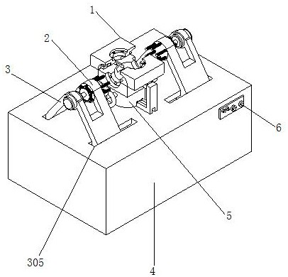
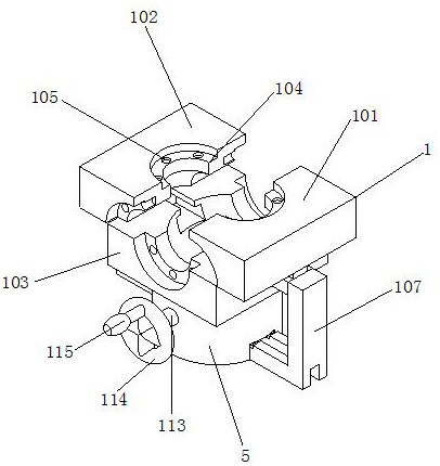
[0030] see Figure 1-3 , the present invention provides a technical solution: a check valve processing equipment, including a fixing device 1, a drilling device 2, a sliding device 3 and a body 4, the inside of the fixing device 1 includes a first fixing block 101 and a second The fixed block 102, the top outer walls of the first fixed block 101 and the second fixed block 102 are slidingly connected with the third fixed block 103, and the outer walls of the first fixed block 101, the second fixed block 102 and the third fixed block 103 are provided with valve grooves 104 , the outer wall of the valve groove 104 is fixedly connected with a tapping hole 105 .
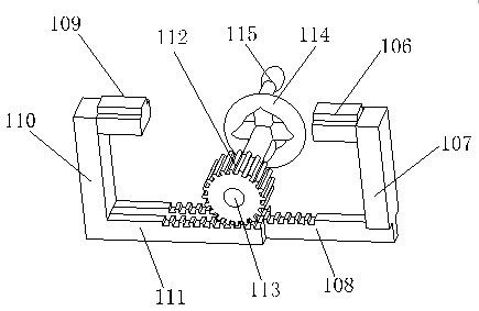
[0031] The bottom outer wall of the first fixed block 101 is fixedly connected with a first connecting block 106, one side outer wall of the first connecting block 106 is fixedly connected with a first support rod 107, and the bottom outer wall of the first support rod 107 is fixedly connected with a first tooth plate 10...
Embodiment 2
[0034] see Figure 1-5As shown, on the basis of Embodiment 1, the present invention provides a technical solution: the inside of the drilling device 2 includes a fixed disc 201, and one side of the outer wall of the fixed disc 201 is rotatably connected with a second gear 202, and the second gear 202 The inner wall of the fixed disk 201 is fixedly connected with a second rotating rod 203, the inner wall of the fixed disk 201 is provided with a limiting groove 204, the inner wall of the fixed disk 201 is rotatably connected with a third rotating rod 205, and the outer wall of the third rotating rod 205 is fixedly connected with a limiting pipe 206, The outer wall of the limiting tube 206 is rotatably connected with the inner wall of the limiting groove 204, and one end of the third rotating rod 205 is fixedly connected with a drilling thread 207, and the outer wall of the third rotating rod 205 is provided with a rotating tooth groove 208, and the rotating tooth groove 208 The ...
Embodiment 3
[0037] see Figure 1-5 As shown, on the basis of Embodiment 1 and Embodiment 2, the present invention provides a technical solution: the interior of the sliding device 3 includes a sliding block 301, and the top outer wall of the sliding block 301 is fixedly connected with a fixing plate 302, and the fixing plate 302 The inner wall of the fixed ring 303 is fixedly connected with a fixed ring 303, the inner wall of the fixed ring 303 is fixedly connected with a motor 304, the output end of the motor 304 is fixedly connected with an end of the second rotating rod 203, and the inner wall of the fixed plate 302 is fixedly connected with the outer wall of the fixed plate 201.
[0038] In this embodiment, by pushing the fixed plate 302, the fixed plate 302 slides inside the body 4 through the sliding block 301, because the fixed plate 302 is fixedly connected with the drilling device 2, so the fixed plate 302 will drive the drilling device 2 to slide, preventing The return valve is ...
PUM
 Abstract
Description
Claims
Application Information
 - R&D
- Intellectual Property
- Life Sciences
- Materials
- Tech Scout
- Unparalleled Data Quality
- Higher Quality Content
- 60% Fewer Hallucinations
Browse by: Latest US Patents, China's latest patents, Technical Efficacy Thesaurus, Application Domain, Technology Topic, Popular Technical Reports.
© 2025 PatSnap. All rights reserved.Legal|Privacy policy|Modern Slavery Act Transparency Statement|Sitemap|About US| Contact US: help@patsnap.com