
Negative pressure die-casting method and device for heat-resistant steel exhaust manifold

An exhaust manifold and heat-resistant steel technology, applied in the field of heat-resistant steel exhaust manifold negative pressure die-casting method and device, can solve the problem of low process yield of 20-30%, large solidification shrinkage of heat-resistant steel material, Problems such as poor fluidity and exhaust manifolds can achieve the effect of improving casting yield and process yield, good structure compactness, and improving process yield

Pending Publication Date: 2021-08-31
GUANGXI KECHUANG MASCH CO LTD
View PDF0 Cites 0 Cited by
  • Summary
  • Abstract
  • Description
  • Claims
  • Application Information

AI Technical Summary

Problems solved by technology

Due to factors such as the poor fluidity of austenitic heat-resistant cast steel and the special structure of the exhaust manifold, the application of austenitic heat-resistant cast steel on the exhaust manifold has great technological difficulties.
The solidification shrinkage of heat-resistant steel material is large, the fluidity of molten steel is poor, and the casting process performance is poor. Castings are prone to casting defects such as pores, slag inclusions, and shrinkage cavities.
At present, most of the austenitic heat-resistant cast steel exhaust manifold adopts the traditional gravity casting process, the pouring temperature is above 1600 ℃, the risers that need to be fed are more and larger, and the casting yield is as low as 70-80% % or less, the yield rate of the process is as low as 20-30%, the production cost is high, and the exhaust manifold with a thin wall of 3-4mm is produced, even if the pouring temperature reaches 1700°C, the casting is difficult to form

Method used


Image

  • Negative pressure die-casting method and device for heat-resistant steel exhaust manifold
  • Negative pressure die-casting method and device for heat-resistant steel exhaust manifold
  • Negative pressure die-casting method and device for heat-resistant steel exhaust manifold

Examples


Embodiment Construction

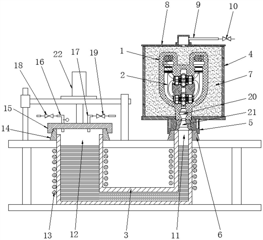
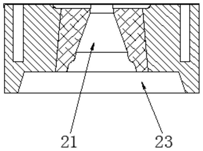
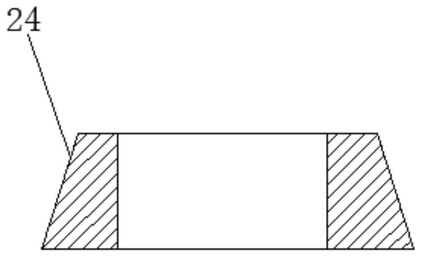
[0034] The present invention will be further described below in conjunction with the specific embodiments in the accompanying drawings.

[0035] refer to Figure 1-3 , a heat-resistant steel exhaust manifold negative pressure die-casting method of the present invention, the method is to put the sand mold into the casting box, then pump air into the casting box to form a negative pressure environment, and finally press molten steel into the casting mold , so as to obtain heat-resistant steel exhaust manifold castings. The method comprises the steps of:

[0036] S1 shell making and core making: use the shell mold to make sand molds on the hot core box machine, and assemble them to get the mold. Specifically, the air sand mold includes the shell and the inner runner core. There are two shells. Finish the paint, dry it, then install the inner runner core into the shell, coat the casting adhesive around the shell, and assemble to form a mold;

[0037] S2 Mold Packing: Put the sa...


PUM


Abstract

The invention discloses a negative pressure die-casting method for a heat-resistant steel exhaust manifold. The negative pressure die-casting method solves the problems that the yield of castings is low and the process yield is low in an existing gravity casting process method. The method comprises the following step of putting a sand mold into a casting box, then exhausting air in the casting box to form a negative pressure environment, and finally pressing molten steel into a casting mold, thereby obtaining a heat-resistant steel exhaust manifold casting. According to the negative-pressure die-casting method for the heat-resistant steel exhaust manifold, the casting yield and the process yield are effectively increased. The invention further discloses a negative pressure die-casting device of the heat-resistant steel exhaust manifold. According to the negative pressure die-casting device for the heat-resistant steel exhaust manifold, the casting yield and the process yield are improved, meanwhile, the production cost is effectively reduced, waste gas is easily treated in a centralized mode, and the purpose of environment-friendly production is achieved.

Description

technical field [0001] The invention relates to a heat-resistant steel exhaust manifold die-casting process, more specifically, it relates to a heat-resistant steel exhaust manifold negative pressure die-casting method and device. Background technique [0002] In recent years, with the rapid development of the automobile industry, the problems of energy and environment have become increasingly prominent, and automobile engines are facing higher challenges in terms of energy conservation and environmental protection. Exhaust manifold is a key part of automobile engine, its quality directly affects the service life and emission performance of the engine. At present, silicon-molybdenum ductile iron and high-nickel cast iron are mostly used as exhaust manifold casting materials. With the improvement of engine performance, the exhaust gas temperature has reached above 900°C, silicon-molybdenum ductile iron and high-nickel ductile iron can no longer meet the performance requireme...

Claims


Application Information

Patent Timeline
Patent Type & Authority Applications(China)
IPC IPC(8): B22D18/04B22D18/06
CPCB22D18/04B22D18/06
Inventor 何海平
Owner GUANGXI KECHUANG MASCH CO LTD
Learn More