
Die-casting machine charging barrel and injection rod

A technology for injection rods and die-casting machines, which is applied in the field of die-casting machine parts, and can solve problems such as long machine standby time, high replacement frequency of injection punches, and high cost of die-casting consumables

Inactive Publication Date: 2021-08-31
常州业能压铸材料有限公司
View PDF6 Cites 0 Cited by
  • Summary
  • Abstract
  • Description
  • Claims
  • Application Information

AI Technical Summary

Problems solved by technology

[0003] The purpose of the present invention is to provide a die-casting machine barrel and injection rod, which aims to improve the replacement frequency of the injection punch in the existing die-casting industry due to the inability to obtain continuous lubrication between the die-casting machine barrel and the injection punch. High, long machine standby time, high cost of die-casting consumables, low production efficiency and other difficult problems

Method used


Image

  • Die-casting machine charging barrel and injection rod
  • Die-casting machine charging barrel and injection rod
  • Die-casting machine charging barrel and injection rod

Examples


Embodiment

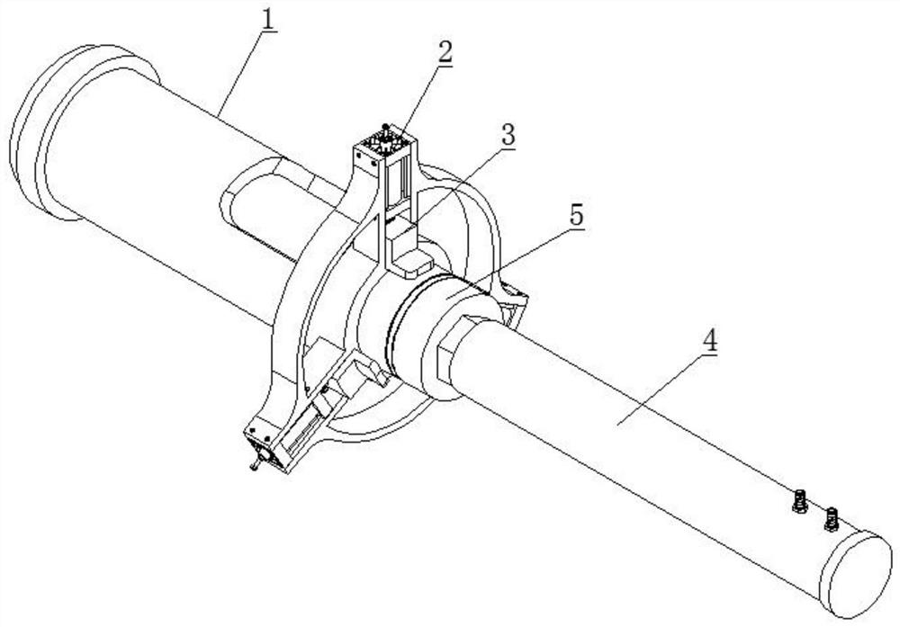
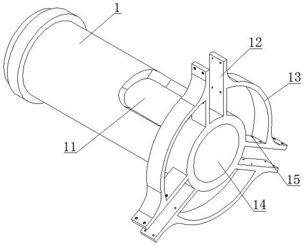
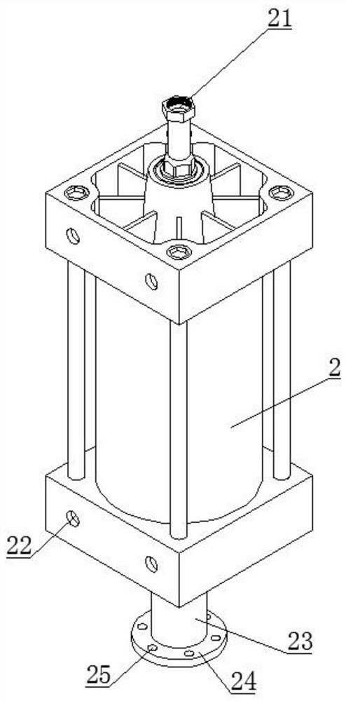
[0025] Example: refer to figure 1 Shown: a die-casting machine barrel and injection rod, including a barrel 1, a number of hydraulic cylinders 2 are uniformly arranged on the front end of the arc surface of the barrel 1, and the hydraulic cylinders 2 and the barrel 1 are connected together by bolts. And the output end of the hydraulic cylinder 2 is provided with a pressure head 3, the pressure head 3 and the output end of the hydraulic cylinder 2 are connected together by bolts, the front end of the barrel 1 is provided with a plunger 4, and the plunger 4 is aligned with the front end of the barrel 1. One end is provided with injection punch 5; barrel 1 is convenient to support the raw material for die-casting, and then it is convenient to carry out die-casting treatment on the raw material; The degree of calibration is corrected, so that the injection punch 5 can be stably used in conjunction with the barrel 1, and the indenter 3 is convenient to be stuck on the arc surface o...


PUM


Abstract

The invention discloses a die-casting machine charging barrel and an injection rod. The structure of the die-casting machine charging barrel and the injection rod comprises a charging barrel, wherein a plurality of hydraulic cylinders are evenly arranged at the front end of the arc face of the charging barrel, the hydraulic cylinders and the charging barrel are connected together through bolts, pressing heads are arranged at the output ends of the hydraulic cylinders, the pressing heads and the output ends of the hydraulic cylinders are connected together through bolts, an injection rod is arranged at the front end of the charging barrel, and an injection plunger is arranged at the end, aligned with the front end of the charging barrel, of the injection rod. By the adoption of the charging barrel and injection rod assembly of the die-casting machine, the problems that in the existing die-casting industry, due to the fact that continuous lubrication cannot be achieved between a die-casting machine charging barrel and the injection plunger, the replacement frequency of the injection plunger is high, the standby time of the machine is long, the consumable cost of die-casting is high, and the production efficiency is high are solved. By improving and optimizing the structure of the die-casting machine charging barrel and the injection rod, the concentricity of the injection plunger and the charging barrel in the injection process is automatically corrected, and meanwhile it is guaranteed that continuous lubrication can be achieved between the injection plunger and the die-casting machine charging barrel when the injection plunger and the die-casting machine charging barrel are used in cooperation.

Description

technical field [0001] The invention relates to the technical field of die-casting machine parts, in particular to a die-casting machine barrel and a plunger. Background technique [0002] A die-casting machine is a series of industrial casting machines that hydraulically inject molten metal into a mold for cooling and forming under pressure, and obtain solid metal castings after the mold is opened. It was originally used for die-casting lead characters. With the development of industries such as automobiles, motorcycles, and household appliances, die-casting technology has developed extremely rapidly in various aspects. The existing die-casting machines have the following problems in the process of use: the existing die-casting industry due to the die-casting machine cylinder Continuous lubrication cannot be obtained between the injection punch and the injection punch, resulting in high replacement frequency of the injection punch, long machine standby time, high cost of di...

Claims


Application Information

Patent Timeline
Patent Type & Authority Applications(China)
IPC IPC(8): B22D17/30B22D17/20
CPCB22D17/30B22D17/2015
Inventor 胡顺兵
Owner 常州业能压铸材料有限公司
Learn More