
Liquid carbon dioxide fracturing pipe millisecond delay control blasting method

A technology of liquid carbon dioxide and carbon dioxide, which is applied in the field of mining or quarrying, can solve problems such as low efficiency, troublesome operation, rock fracture and looseness, and achieve the effects of ensuring safety, saving use costs, and reducing the seismic effect of blasting

Active Publication Date: 2021-08-27
CHINA NAT CHEM ENG HEAVY MECHANIZED CORP +1
View PDF9 Cites 1 Cited by
  • Summary
  • Abstract
  • Description
  • Claims
  • Application Information

AI Technical Summary

Problems solved by technology

[0002] The carbon dioxide fracturing tube is a kind of liquid carbon dioxide fracturing tube that uses liquid carbon dioxide to undergo phase change when heated, and generates an expansion pressure of more than 150Mpa inside the fracturing tube, thereby breaking the tube wall, and the released high-pressure gas has an impact on the surrounding rock medium, thereby causing the rock to crack. The fracture is loose, and the carbon dioxide emitted by the blasting will not produce sparks and will not cause coal mine gas and coal dust explosion accidents, so it has a wide application prospect in China; diameter of the blast hole, and then place the carbon dioxide cracking tube inside the blast hole, and then use concrete plugs to block the top of the blast hole, and blast after the plug reaches its early strength. , and it is necessary to wait for the concrete to solidify before blasting, which is cumbersome and inefficient

Method used


Image

  • Liquid carbon dioxide fracturing pipe millisecond delay control blasting method
  • Liquid carbon dioxide fracturing pipe millisecond delay control blasting method
  • Liquid carbon dioxide fracturing pipe millisecond delay control blasting method

Examples


Embodiment Construction

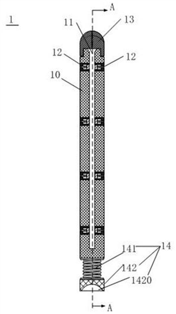
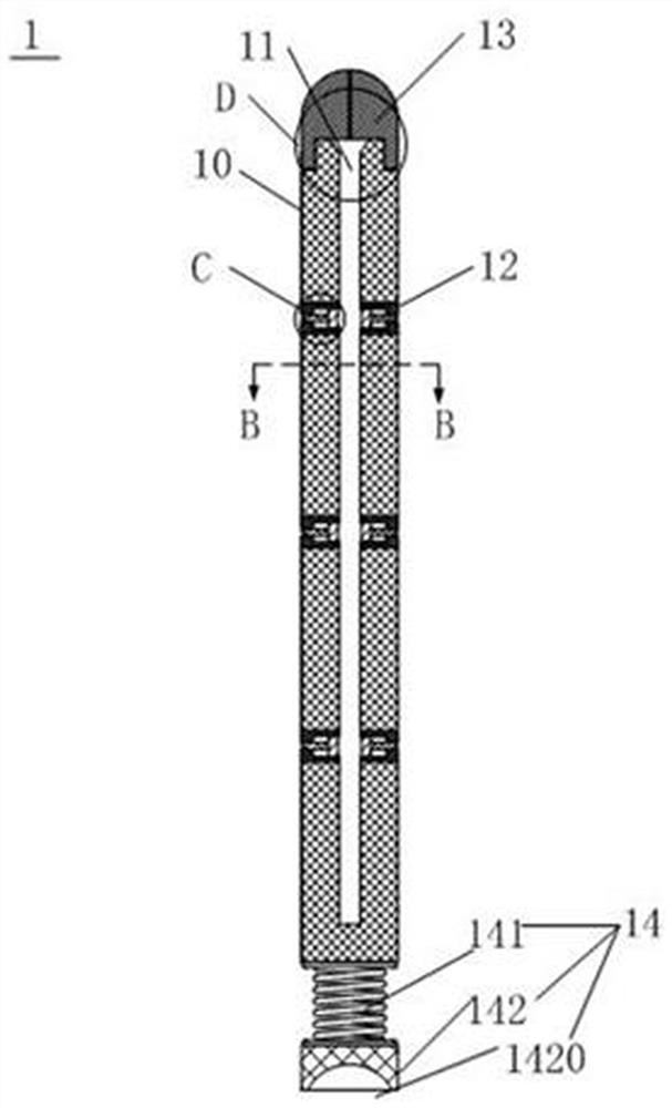
[0034] The application will be further described in detail below in conjunction with the accompanying drawings and embodiments. It should be understood that the specific embodiments described here are only used to explain related inventions, rather than to limit the invention. It should also be noted that, for ease of description, only parts related to the invention are shown in the drawings.

[0035] It should be noted that, in the case of no conflict, the embodiments in the present application and the features in the embodiments can be combined with each other. The present application will be described in detail below with reference to the accompanying drawings and embodiments.

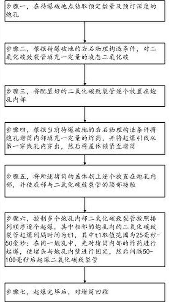
[0036] The invention provides a liquid carbon dioxide cracking tube micro-delay control blasting method, reference figure 1 , Figure 7 , including the following steps:

[0037] Step 1, drilling a predetermined number and predetermined depth of blastholes 31 at the site to be blasted; the number...


PUM


Abstract

The invention belongs to the technical field of mining or quarrying, and provides a liquid carbon dioxide fracturing pipe millisecond delay control blasting method. The method comprises the following steps that firstly, a preset number of blast holes with a preset depth are drilled in a to-be-blasted ground; secondly, a carbon dioxide fracturing pipe is filled with a certain amount of liquid carbon dioxide; thirdly, the carbon dioxide fracturing pipes are placed in the blast holes one by one; fourthly, a certain amount of explosives fill blast hole blocking barrels according to the rock physical structure condition of the current to-be-blasted ground, and then cover bodies are locked to the blocking barrels; fifthly, the configured blocking barrels are arranged in the blast holes; sixthly, the carbon dioxide fracturing pipes and the blocking barrels in the multiple blast holes are controlled to be detonated one by one according to the arrangement sequence; and seventhly, after detonating is completed, the blocking barrels are recycled. The method has the beneficial effects that the blast holes are sealed through the blocking barrels, the blocking barrels can be recycled after blasting, and concrete does not need to be dried when the blocking barrels are used, so that the construction flexibility is improved, and the working efficiency is improved.

Description

technical field [0001] The invention belongs to the technical field of mining or quarrying, and in particular relates to a liquid carbon dioxide cracking tube differential delay control blasting method. Background technique [0002] The carbon dioxide fracturing tube is a kind of liquid carbon dioxide fracturing tube that uses liquid carbon dioxide to undergo phase change when heated, and generates an expansion pressure of more than 150Mpa inside the fracturing tube, thereby breaking the tube wall, and the released high-pressure gas has an impact on the surrounding rock medium, thereby causing the rock to crack. The fracture is loose, and the carbon dioxide emitted by the blasting will not produce sparks and will not cause coal mine gas and coal dust explosion accidents, so it has a wide application prospect in China; diameter of the blast hole, and then place the carbon dioxide cracking tube inside the blast hole, and then use concrete plugs to block the top of the blast ho...

Claims


Application Information

Patent Timeline
IPC IPC(8): F42D3/04F42D1/00F42D1/08
CPCF42D3/04F42D1/00F42D1/08
Inventor 刘孝义于建新马晓华袁海梁崔亚学穆立东袁伟董斌刘攀刘元宝刘星涛
Owner CHINA NAT CHEM ENG HEAVY MECHANIZED CORP
Learn More