Intercepting type gutter inlet device

A technology for gullies and rainwater, which is applied in water supply installations, drinking water installations, general water supply conservation, etc., and can solve problems affecting treatment efficiency and effect, and pollution of downstream receiving water bodies

Active Publication Date: 2021-08-27
WUHAN MUNICIPAL ENG DESIGN & RES INST
View PDF4 Cites 0 Cited by
  • Summary
  • Abstract
  • Description
  • Claims
  • Application Information

AI Technical Summary

Problems solved by technology

During the rainfall process, as the duration of the rainfall increases, the amount of rainfall continues to increase, while the pollutants in the air and on the ground are less and less washed away with the continuous rainfall, and the corresponding pollutants in the air and on the ground carried by the rainwater Therefore, the content of pollutants in the rainwater is not the same at different cumulative rainfalls corresponding to different rainfall durations during the rainfall process. Traditional gully devices do not classify and intercept road surface rainwater at different cumulative rainfalls. Collect and discharge, but collect all the rainwater from the road and discharge it into the downstream pipeline and into the downstream rainwater treatment facilities for treatment. This makes the downstream rainwater treatment facilities unable to target different cumulative rainfall corresponding to different rainfall durations Classified treatment of road rainwater with different pollution levels from time to time, which affects its treatment efficiency and effect, and leads to pollution of the downstream receiving water body discharged after treatment

Method used


Image

  • Intercepting type gutter inlet device
  • Intercepting type gutter inlet device
  • Intercepting type gutter inlet device

Examples


Embodiment Construction

[0031] The principles and features of the present invention are described below in conjunction with the accompanying drawings, and the examples given are only used to explain the present invention, and are not intended to limit the scope of the present invention.

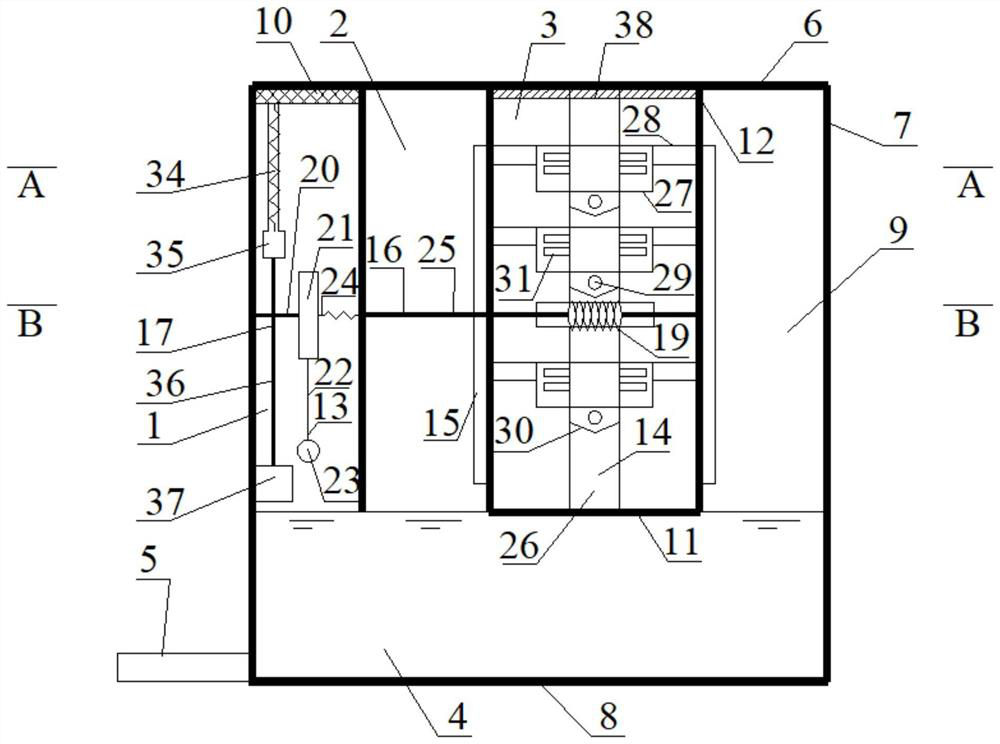
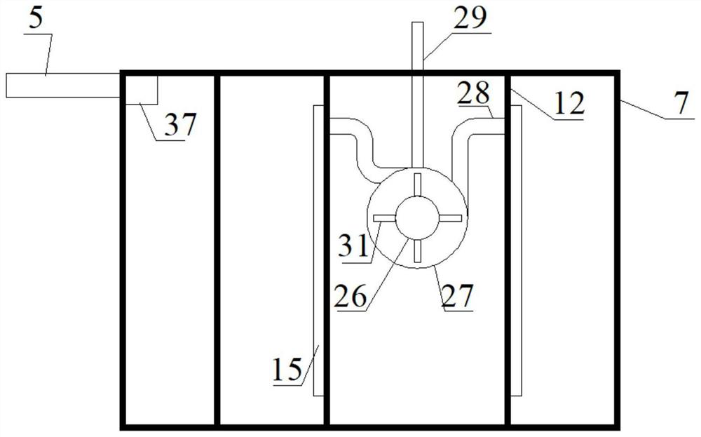
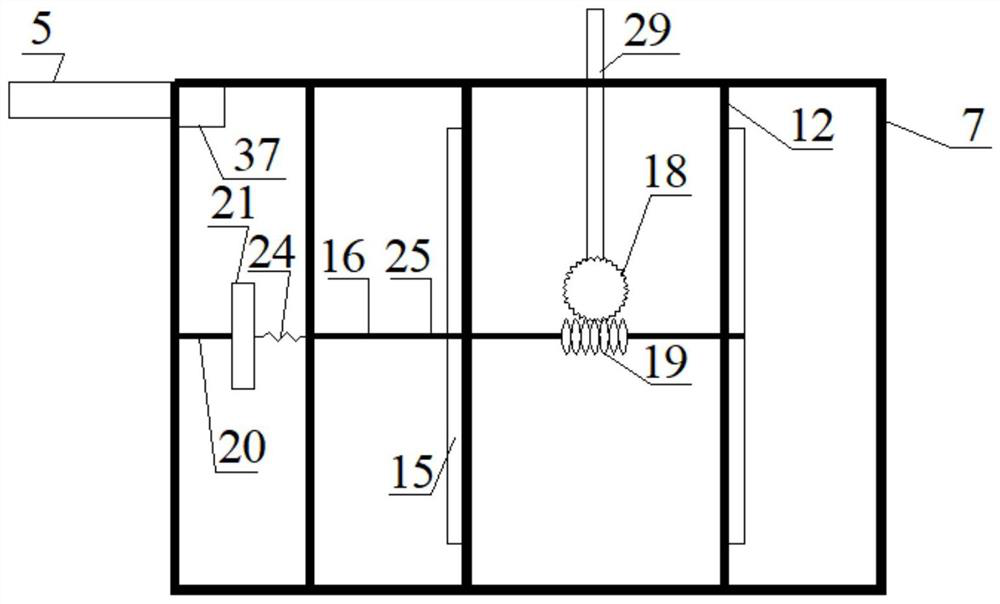
[0032] like Figure 1 to Figure 5 As shown, a shut-off gully device includes a well cavity 9 closed around and a permeable well cover 10. The upper part of the well cavity 9 is adjacently provided with a water inlet chamber 1, a water passage chamber 2 and a diversion chamber 3, which are located at the A water outlet turntable 15 for opening or closing the channels of the two passages is provided on one side of the adjacent side walls of the water passage chamber 2 and the diversion chamber 3 in the water passage chamber 2, and the lower part of the well cavity 9 is provided with a communication pipe. chamber 4, and the water inlet chamber 1 and the water passage chamber 2 communicate with the communication chamber...


PUM


Abstract

The invention relates to an intercepting type gutter inlet device which comprises a well cavity with the periphery closed and a permeable well lid; a water inlet chamber, a water passing chamber and a flow dividing chamber are adjacently arranged on the upper portion in the well cavity; water outlet rotating discs used for opening or closing channels of the water passing chamber and the flow dividing chamber are arranged on the adjacent side walls of the water passing chamber and the flow dividing chamber; a communicating chamber is arranged on the lower portion in the well cavity; the water inlet chamber and the water passing chamber are communicated with the communicating chamber; the permeable well lid is arranged at the top of the water inlet chamber and used for allowing external rainwater to enter into the water inlet chamber; a water drainage pipe used for water drainage is arranged at the bottom of the side wall of the communicating chamber; a water outlet pipe used for water drainage is arranged on the side wall of the flow dividing chamber; and a water inlet mechanism, a drainage mechanism, a water outlet mechanism, a rotating mechanism, a transmission mechanism and the like are arranged in the well cavity. According to the intercepting type gutter inlet device, by means of the water inlet chamber, the water passing chamber, the flow dividing chamber and the related mechanisms arranged in the well cavity, road surface rainwater with different pollution degrees in different rainfall stages can be automatically classified and intercepted, so that a subsequent rainwater treatment facility can conduct targeted treatment conveniently, and then the water quality of a downstream receiving water body is protected.

Description

technical field [0001] The invention relates to the technical field of supporting facilities for municipal drainage rainwater outlets, in particular to a intercepting rainwater outlet device. Background technique [0002] The urban rainwater pipe network system collects rainwater from the road surface through the rainwater collection facility at the beginning - the rainwater outlet device, and then discharges it into the rainwater main pipe, and then transports it to the terminal treatment facility for treatment and then discharges it into the downstream receiving water body. The rainwater pipe network system is the most important facility for collecting road rainwater. The quality of the collected road rainwater will directly affect the operation of the system. During the rainfall process, as the duration of the rainfall increases, the amount of rainfall continues to increase, while the pollutants in the air and on the ground are less and less washed away with the continuou...

Claims


Application Information

Patent Timeline
Patent Type & Authority Applications(China)
IPC IPC(8): E03B3/02E03F5/04E03F5/06E03F5/10E03F5/14
CPCE03B3/02E03F5/04E03F5/0401E03F5/041E03F5/06E03F5/10E03F5/101E03F5/105E03F5/102E03F5/14Y02A20/108
Inventor 李尔曾祥英
Owner WUHAN MUNICIPAL ENG DESIGN & RES INST
Why Eureka
Try Eureka