Thermal power plant desulfurization wastewater treatment system

A technology for desulfurization wastewater and treatment system, applied in energy wastewater treatment, gaseous discharge wastewater treatment, water/sewage treatment, etc. , to achieve the effect of preventing dirt hardening

Active Publication Date: 2022-05-17
HANGZHOU BEISITE ENERGY SAVING & ENVIRONMENT PROTECTION TECH
View PDF0 Cites 0 Cited by
  • Summary
  • Abstract
  • Description
  • Claims
  • Application Information

AI Technical Summary

Problems solved by technology

[0004] First, the desulfurization wastewater of thermal power plants is mainly neutralized, clarified and flocculated by the triple box, and then discharged into clear water after being concentrated by the concentrator. The quality of the clear water discharged in this way is not stable, and it often contains more Metal ions (Mg²+, Ca²+) and SiO 2 If it is not removed, the discharge will not meet the standard. Filter through the microfiltration membrane to remove metal ions. Solid dirt will gradually adhere to and deposit in the filter membrane. The deposition of solid dirt will cause the pores of the microfiltration membrane to be blocked and reduce the filtration efficiency.
[0005] Second, the existing way to solve the clogging of the microfiltration membrane is to perform backwashing to remove the dirt in the microfiltration membrane. Flushing will cause great damage to the microfiltration membrane, resulting in a rapid decline in the life of the microfiltration membrane
[0006] Third, when the existing equipment backwashes the microfiltration membrane, the equipment needs to be shut down. During the cleaning process, the wastewater cannot be filtered at the same time, which greatly hinders the wastewater treatment work and reduces the effluent treatment. efficiency

Method used


Image

  • Thermal power plant desulfurization wastewater treatment system
  • Thermal power plant desulfurization wastewater treatment system
  • Thermal power plant desulfurization wastewater treatment system

Examples


Embodiment Construction

[0039] The following will be combined with Figure 1 to Figure 8The present invention is described in detail, and the technical solutions in the embodiments of the present invention are clearly and completely described. Apparently, the described embodiments are only some of the embodiments of the present invention, not all of them. Based on the embodiments of the present invention, all other embodiments obtained by persons of ordinary skill in the art without making creative efforts belong to the protection scope of the present invention.

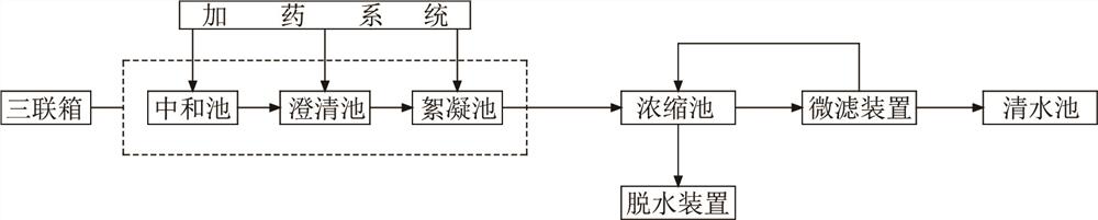
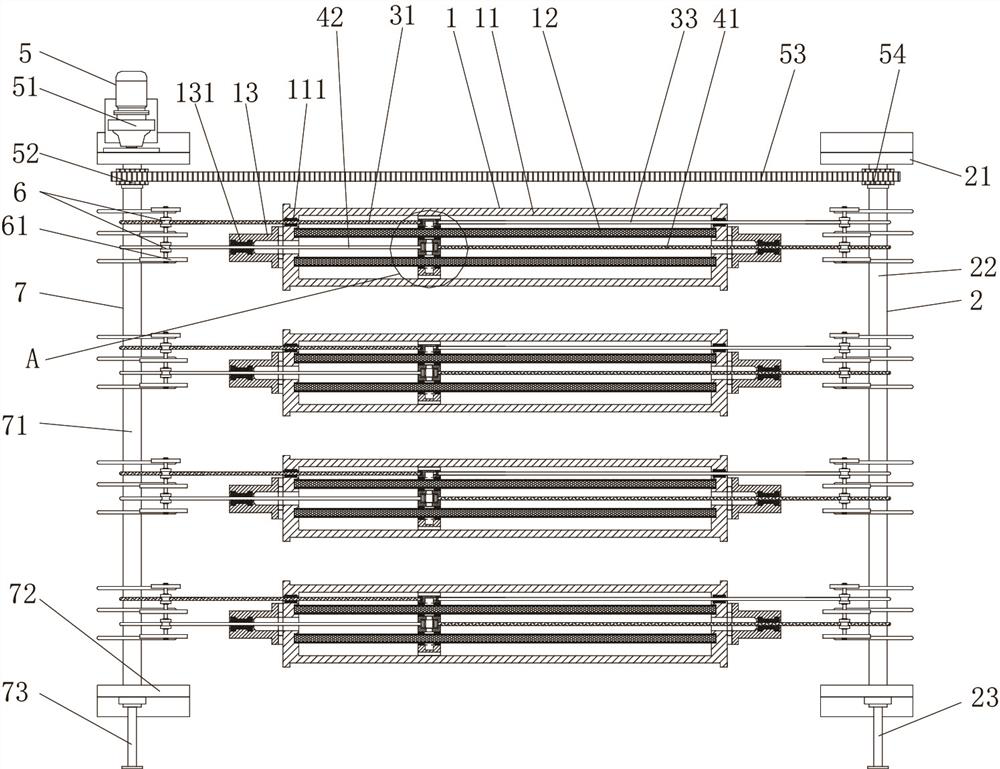
[0040] The present invention provides thermal power plant desulfurization waste water treatment system here by improving, as Figure 1-Figure 8 As shown, it includes a thermal power plant desulfurization wastewater treatment system, including a triple box, the outlet of the triple box is connected to a concentration pool, and the outlet of the concentration pool is connected to a dehydration device and a microfiltration device. The microfil...


PUM


Abstract

The thermal power plant desulfurization wastewater treatment system of the present invention comprises a triple box, the outlet of the triple box is connected with a concentration pool, and the outlet of the concentration pool is connected with a dehydration device and a microfiltration device, and the microfiltration device includes a tubular microfilter, a movable reactor flusher and movable sewage device, the movable recoil device is slidingly arranged in the middle of the tubular microfiltration membrane in the middle of the tubular microfilter, the movable sewage device is sleeved outside the tubular microfiltration membrane, and the position of the movable sewage device is the same as that of the movable recoil device corresponding to the location. In the present invention, the inner wall of the tubular microfilter can be backwashed through the movable recoil device, and the movable sewage discharger can cooperate with the movable recoil device to receive the dirt washed down, due to the movable recoil device and the movable sewage discharge The filter only covers a small part of the tubular microfilter, so that the flushing and filtering work can be carried out at the same time, and the flushing can be carried out in real time, thereby preventing the fouling problem caused by the long-term use of the tubular microfilter.

Description

technical field [0001] The invention relates to the technical field of a thermal power plant desulfurization wastewater treatment system, in particular to a thermal power plant desulfurization wastewater treatment system. Background technique [0002] Desulfurization wastewater is mainly the discharge water from the absorption tower in the process of boiler flue gas wet desulfurization (limestone / gypsum method). In order to maintain the balance of substances in the slurry circulation system of the desulfurization unit, prevent the soluble part of the flue gas, that is, the chlorine concentration from exceeding the specified value, and ensure the quality of gypsum, a certain amount of wastewater must be discharged from the system. The wastewater mainly comes from the gypsum dehydration and cleaning system. The impurities contained in wastewater mainly include suspended solids, supersaturated sulfite, sulfate and heavy metals, many of which are the first category of pollutants...

Claims


Application Information

Patent Timeline
Patent Type & Authority Patents(China)
IPC IPC(8): C02F9/04B01D65/02C02F103/18
CPCC02F9/00B01D65/02C02F2103/18C02F1/66C02F1/52C02F1/444C02F2303/14B01D2321/04Y02W10/37
Inventor 刘晓敏吕俊杰赵玉微
Owner HANGZHOU BEISITE ENERGY SAVING & ENVIRONMENT PROTECTION TECH
Why Eureka
Try Eureka