Device and method for feeding and discharging of LNG cylinders in processing area

A processing area, material feeding and discharging technology, applied in the directions of transportation and packaging, conveyors, mechanical conveyors, etc., can solve the problem that the workpiece enters the processing area with a long rotation time period, reduces production efficiency and profit output, and is not suitable for LNG cylinder transfer. and other problems to achieve the effect of reducing floor space, simple structure and improving production efficiency

Active Publication Date: 2021-08-27
CHINA UNITED ENG
View PDF8 Cites 0 Cited by
  • Summary
  • Abstract
  • Description
  • Claims
  • Application Information

AI Technical Summary

Problems solved by technology

[0003] At present, there are many automatic production lines for LNG cylinders put into use in China. After a detailed investigation of the solutions for the automatic production lines of LNG cylinders disclosed in the market, it is found that the general rule is that a long time is often required between processing equipment. The transfer line usually adopts a unified plane and multi-row parallel layout structure. There are only 1 or 2 processing equipment in a single line of production line, and the workpiece enters the processing equipment line from the main conveying line. The processing area has a long turnaround time period and scattered equipment structure, which occupies a large area, greatly reducing production efficiency and profit output
There are some equipment used for pipe transportation in the prior art, such as the patent with the authorized notification number CN106626153B, which discloses a support transfer platform for pipes, which is suitable for the transmission of long pipes, but it is not suitable for LNG gas. Transfer of bottles between processing stations and infeed and outfeed conveyor lines

Method used


Image

  • Device and method for feeding and discharging of LNG cylinders in processing area
  • Device and method for feeding and discharging of LNG cylinders in processing area
  • Device and method for feeding and discharging of LNG cylinders in processing area

Examples


Embodiment 1

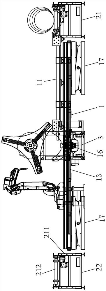
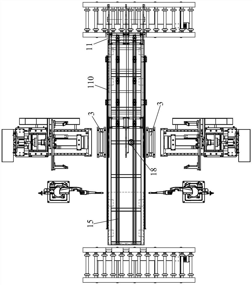
[0053] see Figure 1 to Figure 7 .

[0054] This embodiment 1 discloses a device for feeding and discharging LNG gas cylinders in the circular seam welding processing area, including a claw-type lifting and translation mechanism 1, a roller conveyor line 21 for feeding, and a roller conveyor line 22 for discharging , and two support frames 3 arranged at the processing station for supporting the LNG cylinder. The roller conveying line 21 for feeding and the roller conveying line 22 for discharging are arranged in parallel on both sides of the processing station; Between the conveying lines 22, and located at the processing station, it is used to feed the support frame 3 on the roller conveying line 21 to the support frame 3, and to unload the LNG gas cylinder from the support frame 3 to the On the roller conveying line 22 for discharging.

[0055] In the first embodiment, the claw-type lifting and translation mechanism 1 includes a claw-type manipulator 11 , a support platfo...

Embodiment 2

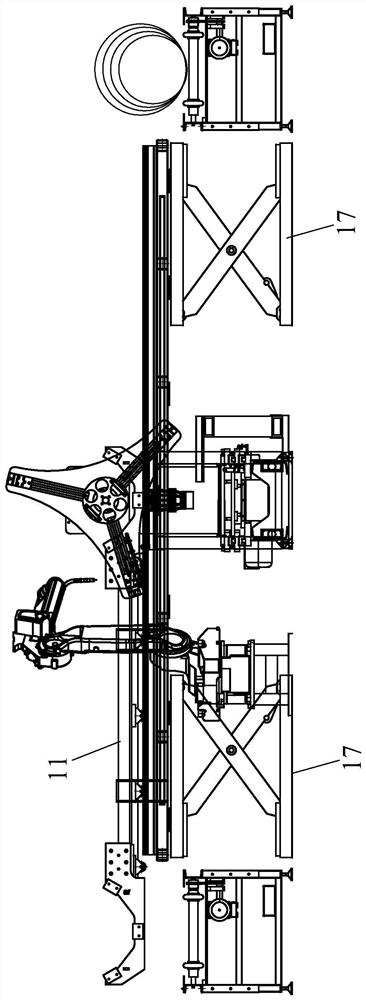
[0064] see Figure 8 to Figure 10 .

[0065] Another device for feeding and discharging LNG gas cylinders in the processing area is disclosed in Embodiment 2, which includes a claw-type jacking translation mechanism 1, a jacking mechanism 4 for LNG gas cylinders, a roller conveyor line 21 for feeding, and a A roller conveying line 22 is used for the material, and at least two support frames 3 arranged at the processing station for supporting the LNG cylinder. The roller conveying line 21 for feeding and the roller conveying line 22 for discharging are arranged in parallel on both sides of the processing station; Frame 211 and a row of conveying rollers 212 installed on the mounting frame 211; the claw-type jacking translation mechanism 1 is arranged between the roller conveying line 21 for feeding and the roller conveying line 22 for discharging, and is located at the processing station It is used to load the support frame 3 on the roller conveyor line 21 for feeding to the ...


PUM


Abstract

The invention relates to a device and method for feeding and discharging of LNG cylinders in a processing area. A roller type conveying line for feeding and a roller type conveying line for discharging are arranged on the two sides of a processing station in parallel. A claw type jacking translation mechanism is arranged between the roller type conveying line for feeding and the roller type conveying line for discharging and located at the processing station. The roller type conveying line for feeding and the roller type conveying line for discharging are of the same structure and each comprise an installation frame and a row of conveying rollers installed on the installation frame. The structural form of each installation frame is one of the following two types that in the first type, a channel is reserved in the installation frame, and in the second type, no channel is arranged on the installation frame, and the feeding position of the roller type conveying line for feeding and the discharging position of the roller type conveying line for discharging are each provided with an LNG cylinder jacking mechanism. The device is wide in application range, simple in structure, convenient to operate and capable of effectively reducing the occupied area of production lines, and the purposes that workpieces on one production line can be rapidly transferred to another production line, and the production efficiency is improved are achieved.

Description

technical field [0001] The invention relates to LNG gas cylinder processing equipment, in particular to a device and method for feeding and discharging LNG gas cylinders in a processing area. Background technique [0002] As a pressure vessel for storage of cryogenic liquids, LNG cryogenic insulating gas cylinders have been widely used at home and abroad. LNG gas cylinders are used as the core equipment of raw material supply systems in many industries. It has the advantages of light weight, large filling capacity, pure gas and liquid, convenient transportation and loading and unloading, and safety and reliability. [0003] At present, there are many automatic production lines for LNG cylinders put into use in China. After a detailed investigation of the solutions for the automatic production lines of LNG cylinders disclosed in the market, it is found that the general rule is that the processing equipment often needs a long time. The transfer line usually adopts a unified p...

Claims


Application Information

Patent Timeline
Patent Type & Authority Applications(China)
IPC IPC(8): B65G47/90B65G37/00
CPCB65G47/90B65G47/901B65G37/00B65G2201/0244
Inventor 章宇庆周炳水王振李艳林瑞进
Owner CHINA UNITED ENG
Why Eureka
Try Eureka