


Quick Research
Generate reliable direction feasibility study reports for your R&D in just a few steps.

Technical Q&A
Discover and master advanced knowledge NOW. Basics, ideas, possibilities, all at once.

Find Solutions
As an expert in R&D theories, this can generate solutions to your technical problems instantly.

Evaluate Feasibility
Analyze your overall solution with one click, know your potential R&D risks in advance.

Monitor Landscape
Get weekly tech updates, stay abreast of the latest tech innovations and key insights.
Steel ball rust removal device for bearing production
A technology for bearing production and steel balls, which is applied to the parts of grinding machine tools, grinding machines, grinding/polishing equipment, etc. It can solve the problems of inability to remove the rust of steel balls, time-consuming, and accumulation of steel balls, so as to achieve convenient and rapid collection. The effect of storage, reducing labor intensity and avoiding waste
- Summary
- Abstract
- Description
- Claims
- Application Information
AI Technical Summary
Problems solved by technology
Method used
Image

Examples
Embodiment 1
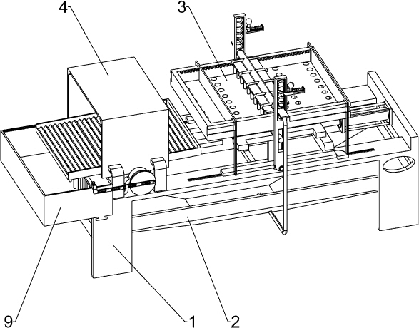
[0032] A steel ball derusting device for bearing production, such as figure 1 As shown, it includes a mounting frame 1, a holding bucket 2, a processing mechanism 3 and a drying mechanism 4. The lower part of the mounting frame 1 is provided with a containing bucket 2, and the mounting frame 1 on the upper side of the holding bucket 2 is provided with a processing mechanism 3. , the mounting frame 1 on the right side of the processing mechanism 3 is provided with a drying mechanism 4 .
[0033]When it is necessary to derust the steel balls, the user pours an appropriate amount of steel balls into the processing mechanism 3, and then the user connects the external pipe to the processing mechanism 3, and inputs the derusting liquid into the processing mechanism 3 through the external pipe, and starts the processing mechanism at the same time 3 works, the processing mechanism 3 works so that the derusting liquid can be evenly sprayed on the steel balls, while the processing mecha...
Embodiment 2
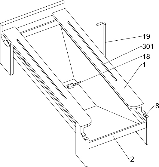
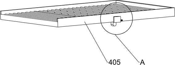
[0035] On the basis of Example 1, such as Figure 2-7 As shown, the processing mechanism 3 sliding plate 302, the first support plate 303, the connecting frame 304, the connecting block 306, the rotating plate 307, the positioning rod 308, the first sliding block 310, the first spring 311, the pushing plate 312, the reciprocating hydraulic cylinder 313, holding frame 314, net plate 317, block 3171, counterweight 318, first pushing plate 319, second pushing plate 320, connecting plate 321, vertical plate 322, rotating shaft 323, support plate 324, turn Spring 325 and sprinkling parts, the front and rear sides of mounting frame 1 top are all provided with first chute 301, and sliding type is provided with slide plate 302 in the first chute 301, and the front and rear sides of mounting frame 1 top are all provided with first chute 301. Support plate 303, the first support plate 303 on the front and rear sides is located between the sliding plates 302 on the front and rear sides, ...
Embodiment 3
[0042] On the basis of Example 2, such as figure 1 , figure 2 and Figure 12 Shown, also comprise disc 5, articulated rod 6, articulated frame 7, collecting box 9, moving plate 10, sharing bar 11 and pin bar 111, the front side output shaft of bidirectional deceleration motor 410 is equipped with disc 5, circle The eccentric position of the front side wall of the disc 5 is rotatably connected with a hinged rod 6, and the articulated rod 6 is rotatably equipped with a hinged frame 7, and the front and rear parts on the left side of the top of the mounting frame 1 are all provided with the fifth sliding groove 8. Slidingly be provided with collecting box 9 between the 5th sliding groove 8, be provided with moving plate 10 slidingly between the front and back side walls in collecting box 9, the bottom of moving plate 10 is equipped with at least three apportioning rods 11, moving plate A pin bar 111 is slidably provided between 10 and the hinged frame 7 .
[0043]When the ste...
PUM
 Abstract
Description
Claims
Application Information
 - R&D Engineer
- R&D Manager
- IP Professional
- Industry Leading Data Capabilities
- Powerful AI technology
- Patent DNA Extraction
Browse by: Latest US Patents, China's latest patents, Technical Efficacy Thesaurus, Application Domain, Technology Topic, Popular Technical Reports.
© 2024 PatSnap. All rights reserved.Legal|Privacy policy|Modern Slavery Act Transparency Statement|Sitemap|About US| Contact US: help@patsnap.com