Brush

A technology of brushes and brush handles, applied in the field of cleaning tools, can solve the problems of inconvenient storage and storage, easy breeding of bacteria, and difficulty in drying, etc., and achieve the effect of convenient storage and storage

Inactive Publication Date: 2018-02-13
杜宇辰
View PDF0 Cites 0 Cited by
  • Summary
  • Abstract
  • Description
  • Claims
  • Application Information

AI Technical Summary

Problems solved by technology

[0002] In the Chinese patent literature, there are disclosed brushes that are particularly suitable for cleaning cooking utensils such as pots and pans. For example, the utility model scrubbing brush is composed of a loofah block and a handle, and the loofah block is fixed on the head of the handle with rivets. The brush of this structure It has an ideal effect on removing oil stains, but there are the following deficiencies: first, it is difficult to remove the stubborn scale attached to the surface of the pot, because the loofah block is a soft body; second, it is easy to cause secondary pollution, because the greasy Attached to the loofah block is easy to pollute the loofah block, and if it is not cleaned, it is easy to breed bacteria; the third is that the loofah block has poor durability and needs to be replaced frequently
Another example is that the brush is composed of a body and a brush body that have a handle and a fixed pin. Although it has the advantage of being able to clean stubborn dirt, this patent solution has the following disadvantages: one is because the brush body is a steel ball, so when in use (During the brushing process) it is easy to shed debris, if it is neglected to remove it, it will easily affect health; second, because the brush body is a very fluffy ball body, the comb-shaped fixing pin is easy to pass through the brush body during use, so that the fixing pin and The direct hard contact of the pot body will damage the pot body (scratch the surface of the pot body); the third is poor sanitation, and the inside of the brush body is often in a wet state, which is difficult to dry, so it is easy to breed bacteria and cause two pollutions; It is separated from the main body when it is not in use, so it is not convenient for storage and storage

Method used


Image

  • Brush

Examples


Embodiment Construction

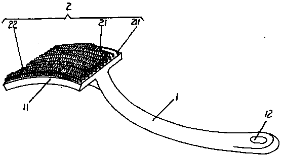
[0007] Please refer to the accompanying drawings, one end of the provided brush handle 1, that is, the right end of the position shown in the figure, has a hanging hole 12, and the other end of the brush handle 1, that is, the left end of the figure, has a brush body positioning plate 11, and the brush body is positioned Plate 11 and brush handle 1 are integrally produced. The brush body 2 is arranged on the surface of one side of the brush body positioning plate 11, and the brush body 2 includes a group of coil positioning bars 21 and a group of coil coils 22, and the quantity of a group of coil coils 22 is the same as that of a group of coil positioning bars 21. The numbers are equal, specifically: a group of coil positioning strips 21 are fixed to the brush body positioning plate 11 through the positioning feet 211 at both ends in the same way, and the adjacent coil positioning strips 21 are kept parallel to each other. A spiral spring ring 22 is sheathed on the positioning...


PUM


Abstract

A brush belongs to the technical field of cleaning appliances. It includes a brush handle and a brush body arranged on the brush handle. One end of the brush handle forms a brush body positioning plate. The brush body includes a spring ring positioning strip and a spring coil. The number of spring coils is the same as that of the spring coil positioning bar. The numbers are equal, and the spring coil positioning strips are fixed on the brush body positioning plate in a spaced state and parallel to each other, and each spring coil positioning strip is sleeved with a spring coil. This technical solution can effectively remove the fouling stubbornly attached to the pot by the spring coil without damaging the surface of the pot. Since the spring coil has a space, it is easy to keep dry without breeding bacteria. The brush handle and the brush body The performance is an integrated structure, which is convenient for collection and storage.

Description

technical field [0001] The invention belongs to the technical field of cleaning appliances, and in particular relates to a brush. Background technique [0002] In the Chinese patent literature, there are disclosed brushes that are particularly suitable for cleaning cooking utensils such as pots and pans. For example, the utility model scrubbing brush is composed of a loofah block and a handle, and the loofah block is fixed on the head of the handle with rivets. The brush of this structure It has an ideal effect on removing oil stains, but there are the following deficiencies: first, it is difficult to remove the stubborn scale attached to the surface of the pot, because the loofah block is a soft body; second, it is easy to cause secondary pollution, because the greasy Attached to the loofah block, it is easy to pollute the loofah block, and if it is neglected to clean, it is easy to breed bacteria; the third is that the loofah block has poor durability and is frequently rep...

Claims


Application Information

Patent Timeline
IPC IPC(8): A47L17/08A46B9/06
CPCA47L17/08A46B9/06A46B2200/3033
Inventor 不公告发明人
Owner 杜宇辰
Why Eureka
Try Eureka