Terminal transfer box applied to field of distribution network automation

A distribution network automation, transfer box technology, applied in the direction of chassis/cabinet/drawer parts, electrical components, circuit devices, etc., can solve the problem of increasing the risk factor of staff, affecting the maintenance of terminal transfer boxes, door body Worker injury and other issues, to achieve the effect of reducing the risk factor, reducing the center of gravity, and increasing safety

Active Publication Date: 2021-08-24
CHANGCHUN POWER SUPPLY COMPANY OF STATE GRID JILINSHENG ELECTRIC POWER SUPPLY
View PDF5 Cites 2 Cited by
  • Summary
  • Abstract
  • Description
  • Claims
  • Application Information

AI Technical Summary

Problems solved by technology

[0004] The terminal transfer box in the prior art is installed in a rectangular box and then installed on the column through a bracket. The terminal transfer box needs regular maintenance and also needs to be repaired when the power grid fails. During maintenance and repair, staff need to climb to the column Only then can the terminal transfer box be repaired. During the maintenance process, if there is a sudden strong wind, the door body will shake around, which will seriously affect the maintenance of the terminal transfer box by the staff, and the shaking door body will not work properly. Injury to personnel, due to the small operating space of the staff on the column, if the staff is distracted to fix the door when encountering strong winds, the staff needs to move a lot, which will greatly increase the risk factor of the staff

Method used


Image

  • Terminal transfer box applied to field of distribution network automation
  • Terminal transfer box applied to field of distribution network automation
  • Terminal transfer box applied to field of distribution network automation

Examples


Embodiment Construction

[0027] The following will clearly and completely describe the technical solutions in the embodiments of the present invention with reference to the accompanying drawings in the embodiments of the present invention. Obviously, the described embodiments are only some, not all, embodiments of the present invention. Based on the embodiments of the present invention, all other embodiments obtained by persons of ordinary skill in the art without creative efforts fall within the protection scope of the present invention.

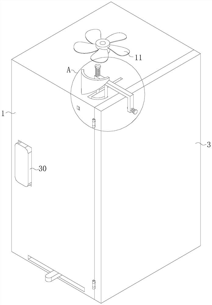
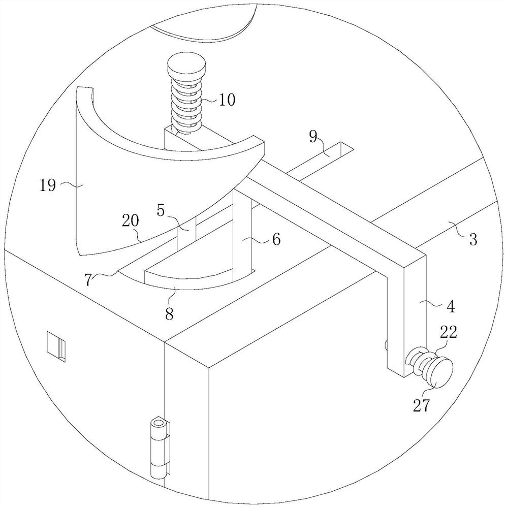
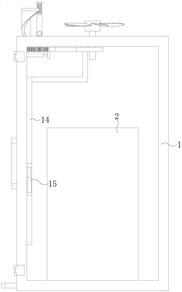
[0028] see Figure 1-7 , the present invention provides a technical solution: a terminal transfer box applied to the field of distribution network automation, including an installation box 1, a terminal transfer box 2 is fixed inside the installation box 1, and the front wall of the installation box 1 passes through Two hinges are hinged with protective door 3, and the top of installation box 1 is provided with closing lever 4, and closing lever 4 is positioned at ...


PUM


Abstract

The invention discloses a terminal transfer box applied to the field of distribution network automation in the technical field of distribution network automation, and the terminal transfer box comprises a mounting box, the terminal transfer box is fixedly arranged in the mounting box, a protective door is hinged to the front wall of the mounting box through two hinges, and a door closing rod is arranged at the top of the mounting box. The door closing rod is located on the side close to the rotating center of the protective door, the initial position of the bottom face of the door closing rod is located above the top of the protective door, and the door closing rod is slidably connected with a first rotating shaft and a second rotating shaft in the vertical direction. The protective door can be automatically fixed when encountering strong wind in the maintenance process, and workers can better carry out maintenance work.

Description

technical field [0001] The invention relates to the technical field of distribution network automation, in particular to a terminal transfer box applied in the field of distribution network automation. Background technique [0002] With the advent of the 5G era, the operating speed of the network will be greatly improved, which will also greatly increase the burden on the power grid. In the distribution network, the distribution network automation master station system has not been established in the early stage. The original line inspection or the GSM SMS mode on the traditional controller can obtain the switch status such as the current and voltage of the switch on the column. [0003] Some invention patents in the field of distribution network automation technology are disclosed in the prior art, among which the invention patent with the application number CN202010500033.8 discloses a universal transfer box for distribution network automation terminals on a column, which ...

Claims


Application Information

Patent Timeline
IPC IPC(8): H05K5/02H02J13/00
CPCH05K5/0217H02J13/00
Inventor 陈国晖魏宏亮郭超时烁王志鹏刘永王春涛索东冬闫天骥马思千
Owner CHANGCHUN POWER SUPPLY COMPANY OF STATE GRID JILINSHENG ELECTRIC POWER SUPPLY
Why Eureka
Try Eureka