
Power supply control device, power supply control method and system

A power control device, power control technology, applied in general control systems, control/regulation systems, program control, etc., can solve problems such as data loss, system damage, computer failure, etc., to prevent data loss and prevent system damage. Effect

Active Publication Date: 2021-08-24
EVOC INTELLIGENT TECH
View PDF11 Cites 0 Cited by
  • Summary
  • Abstract
  • Description
  • Claims
  • Application Information

AI Technical Summary

Problems solved by technology

[0003] However, the power control part in the existing CPLD is only designed with a key detection module and a power control module, and there is no information feedback channel from the CPLD to the CPU
[0004] This will make electronic equipment, especially computers based on certain CPU platforms, such as Feiteng platform, XX platform, etc., in the state of being turned on, the CPLD therein detects that by pressing the power button of the computer based on certain CPU platforms For the generated signal, computers based on certain CPU platforms generally have two processing methods for pressing the power button.
The second is that the CPLD will directly control the mainboard power outage through the power control module. At this time, the operating system of the computer based on some CPU platforms does not know that the mainboard will be powered off. This will make most computers, especially based on some CPUs. The computer on the platform will not perform operations such as closing programs and saving data before shutting down, so there is a risk of data loss and system damage

Method used


Image

  • Power supply control device, power supply control method and system
  • Power supply control device, power supply control method and system
  • Power supply control device, power supply control method and system

Examples


Embodiment Construction

[0087] In order to make the purpose, technical solutions and advantages of the embodiments of the present invention clearer, the technical solutions in the embodiments of the present invention will be clearly and completely described below in conjunction with the drawings in the embodiments of the present invention. Obviously, the described embodiments It is only some embodiments of the present invention, but not all embodiments. Based on the embodiments of the present invention, all other embodiments obtained by those skilled in the art without making creative efforts belong to the protection scope of the present invention.

[0088] First, explain the proper nouns involved in this application, as follows:

[0089] LPC: Low pin count Bus, the communication bus that the CPU connects to low-speed peripherals.

[0090] EC: Embedded Controller, embedded controller.

[0091] ACPI: Advanced Configuration and Power Management Interface, Advanced Configuration and Power Management I...


PUM


Abstract

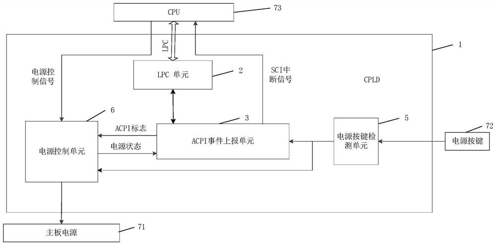
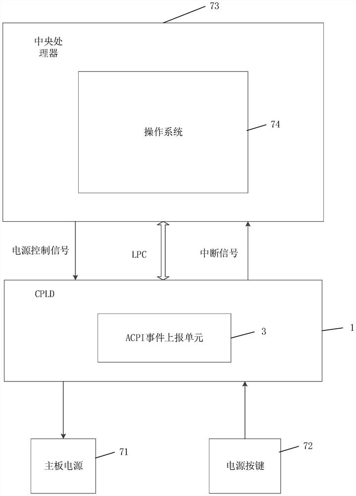
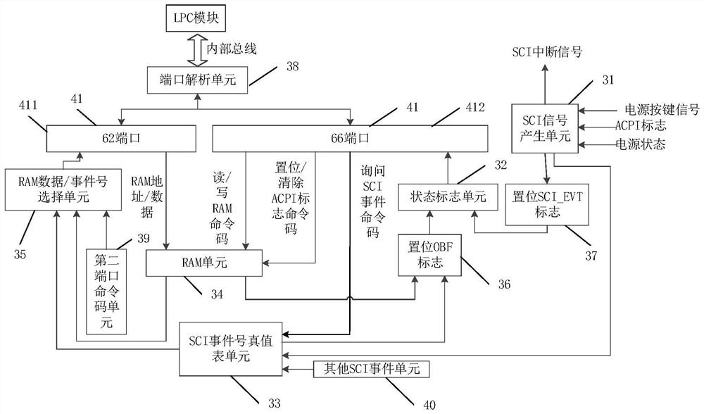
The invention provides a power supply control device, a power supply control method and a power supply control system. The power supply control device comprises a protocol conversion module, an event reporting module, a target event detection module and a power supply control module; the target event detection module is in communication connection with the event reporting module and the power supply control module, and the protocol conversion module is in communication connection with the event reporting module; the target event detection module is used for sending a target event signal to the event reporting module and the power supply control module; the protocol conversion module is used for analyzing a communication frame protocol of the operating system and the power supply control device; the event reporting module is used for notifying an operation system of the executed event of the target event through the protocol conversion module, so that the operation system performs safe shutdown operation and sends a power supply control signal; and the power supply control module is used for powering off a mainboard power supply. According to the invention, when the mainboard power supply is powered off, data loss and system damage can be prevented.

Description

technical field [0001] The present invention relates to the technical field of digital integrated circuits, in particular to a power control device, a power control method and a system. Background technique [0002] In the process of using CPLD (Complex Programming logic device, complex programmable logic device) to control the shutdown of electronic equipment in existing electronic equipment, usually when the CPLD detects a shutdown trigger signal, the CPLD directly controls the mainboard power supply through the power control module. power off. Wherein, the shutdown trigger signal includes: a signal generated by pressing a power key of the electronic device, and a signal capable of triggering the shutdown of the electronic device generated by closing the cover of the electronic device. [0003] However, the power control part of the existing CPLD is only designed with a key detection module and a power control module, and there is no information feedback channel from the ...

Claims


Application Information

Patent Timeline
IPC IPC(8): G05B19/042
CPCG05B19/0423G05B2219/25257
Inventor 丁皓江广浪陈志列庞观士
Owner EVOC INTELLIGENT TECH
Learn More