Grinding and polishing device for window rubber roller
A polishing device and rubber technology, applied in the direction of grinding/polishing safety device, grinding drive device, grinding/polishing equipment, etc., can solve the problems of manpower consumption, low work efficiency, cumbersome operation process, etc., and improve work efficiency , Simple operation, labor-saving effect
- Summary
- Abstract
- Description
- Claims
- Application Information
AI Technical Summary
Problems solved by technology
Method used
Image
Examples
Embodiment 1
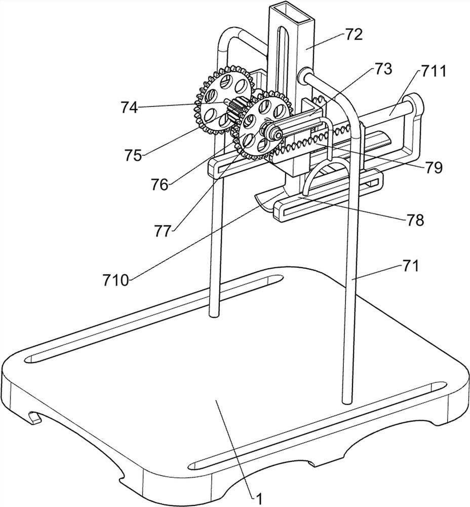
[0031] A windows rubber pulley for polishing a polishing device, such as Figure 1-3 As shown, the bottom plate 1, the mounting frame 2, and the limit shaft 3 are shown, and the bottom plate 1 side is connected to the mounting frame 2, and the mounting frame 2 is connected to the finite axis 3, further comprising a rotating mechanism 4 and a grinding mechanism. 5. The mounting frame 2 is provided with a rotating mechanism 4 and a grinding mechanism 5.
[0032] The rotating mechanism 4 includes a servo motor 41, a rotating shaft 42, and a first rotary wheel 43, and a servo motor 41 is attached to the right side of the mounting frame. The shaft 42 is connected to the output shaft of the servo motor 41, and the rotating shaft 42 is connected to the first rotary wheel. 43.
[0033] The grinding mechanism 5 includes a first connecting shaft 51, a second connecting shaft 52, a straight gear group 53, a second rotary wheel 54, a grinding wheel belt 55, and a flat belt transmission assembl...
Embodiment 2
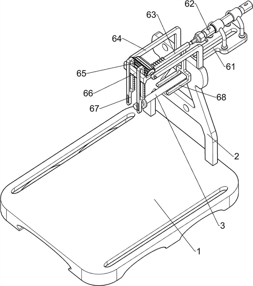
[0036] On the basis of Example 1, such as Figure 4 As shown, it is also included, and the carrier mechanism 6 includes a first fastener 61, a cylinder 62, a first rack 63, a first support frame 64, a first transmission straight gear 65, a guide block 66, The second rack 67 and the first rod 68 are connected to the right side of the mounting frame 2, and the first fastener 61 is attached to the first retaining frame 61, and the first rack 63 is connected to the telescopic rod of the cylinder 62. The top of the mounting frame 2 is connected to the first support frame 64, and the first support frame 64 is rotated with the first transmission straight gear 65, and the first support frame 64 is connected to the guide slider 66, and the guide slider 66 has both front and rear sides. The sliding-type connection has a second rack 67, and the second rack 67 meshes with the first transmission straight gear 65, and the first rod 68 is connected to the first rack 63.
[0037]When the rubber pu...
Embodiment 3
[0041] On the basis of Example 2, such as Figure 7 As shown, there is a dust removal mechanism 8, and the dust removal mechanism 8 includes a second guide carriage 81, a dust box 82, and a brush 83, and a second guide carriage 81 is connected to the top of the bottom plate 1, and the second guide carriage 81. The upper sliding is connected to the dust box 82, and the dust box 82 is detachable, and a brush 83 is connected to the dust box 82, and the brush 83 is in contact with the grinding wheel belt 55.
[0042] When the grinding wheel belt 55 can be cleaned by the brush 83, the grades generated during cleaning fall within the dust box 82, and when the dust box 82 will be pulled out, the dust box 82 can be pulled out. Then remove the ash inside the dust box 82.
[0043] like Figure 8 As shown, there is a surface of the attachment mechanism 9, and the refryrome 9 includes a bridge 91, a third fixing frame 92, and an oblique carriage 93. The top left side of the bottom plate frame 1...
PUM
 Abstract
Description
Claims
Application Information
 - R&D
- Intellectual Property
- Life Sciences
- Materials
- Tech Scout
- Unparalleled Data Quality
- Higher Quality Content
- 60% Fewer Hallucinations
Browse by: Latest US Patents, China's latest patents, Technical Efficacy Thesaurus, Application Domain, Technology Topic, Popular Technical Reports.
© 2025 PatSnap. All rights reserved.Legal|Privacy policy|Modern Slavery Act Transparency Statement|Sitemap|About US| Contact US: help@patsnap.com


