
Machining method for grinding high-strength aeronautical part through numerical control machining center

A technology for aerospace parts and machining centers, which is applied in the direction of grinding workpiece supports, grinding machine parts, grinding drive devices, etc. Inexpensive, low runout, short shank length effects

Inactive Publication Date: 2021-08-24
成都爱乐达航空制造股份有限公司
View PDF10 Cites 0 Cited by
  • Summary
  • Abstract
  • Description
  • Claims
  • Application Information

AI Technical Summary

Problems solved by technology

High-strength steel parts have precise outer circle dimensions, precise groove width dimensions, and precise wall thickness dimensions. Due to product structure constraints, such dimensions cannot be processed by grinding machines, lathes, and boring machines.
During CNC milling, due to factors such as tool jump, machine tool jump, large length-to-diameter ratio of the processing tool, machining gap, tool wear and other factors, it is impossible to process such precision dimensions to pass

Method used


Image

  • Machining method for grinding high-strength aeronautical part through numerical control machining center
  • Machining method for grinding high-strength aeronautical part through numerical control machining center
  • Machining method for grinding high-strength aeronautical part through numerical control machining center

Examples


Embodiment 1

[0044] like Figure 4 to Figure 6 As shown in the figure, the machining method of grinding high-strength aerospace parts by CNC machining center includes the following steps:

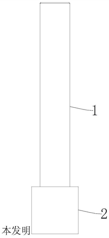
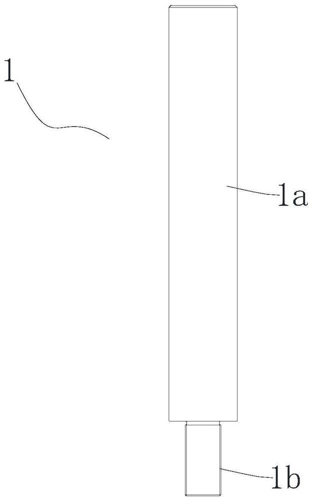
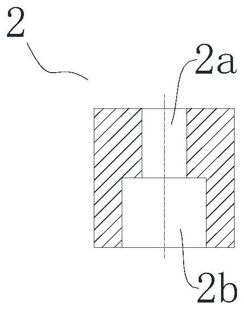
[0045] S1. Clamping: Clamp the product 5 on the worktable 3, clamp one end of the tool bar 1 on the machine tool spindle 4, and clamp the grinding wheel 2 at the other end;

[0046] S2. The grinding wheel 2 is rotated through the rotation of the machine tool spindle 4, the speed S is 8000~10000r / min, and the XY axis of the machine tool is linked to feed, the feed rate F is 100~120mm / min, and the grinding surface is the two sides of a certain type of landing gear. There are two parallel planes, the movement track of grinding wheel 2 is parallel to the grinding surface, adjust the knife compensation value, according to the difference between the actual value and the required value, and then select the appropriate number of knife compensation values, and control each knife compensation within 0.05mm, Diff...

Embodiment 2

[0052] like Figure 7 to Figure 9 As shown in the figure, the machining method of grinding high-strength aerospace parts by CNC machining center includes the following steps:

[0053] S1. Clamping: Clamp the product 5 on the worktable 3, clamp one end of the tool bar 1 on the machine tool spindle 4, and clamp the grinding wheel 2 at the other end;

[0054] S2. The grinding wheel 2 is rotated by the rotation of the machine tool spindle 4, the speed S is 8000~10000r / min, and the XY axis of the machine tool is linked to feed, the feed rate F is 100~120mm / min, and the grinding surface is a certain type of landing gear. Cylindrical surface, the movement trajectory of grinding wheel 2 is parallel to the grinding surface, that is, the movement trajectory of grinding wheel 2 is circular, adjust the tool compensation value so that the cylinder of the part is guaranteed to be ∅60 (-0.10 / -0.126) mm, ∅60.5 (-0.10 / -0.126) mm, preferably, the parameter is F=100mm / min.

[0055] Further, i...


PUM


Abstract

The invention relates to a machining method for grinding a high-strength aeronautical part through a numerical control machining center, which. The machining method comprises the following steps that S1, clamping is carried out, a product is clamped on a workbench, one end of a cutter bar is clamped on a machine tool spindle, and a grinding wheel is clamped at the other end; and S2, a main shaft of a machine tool rotates to drive the grinding wheel to rotate, the rotating speed S ranges from 8000 r / min to 10000 r / min, through linkage feeding of the X axis and the Y axis of the machine tool, the feeding amount F ranges from 100 mm / min to 120 mm / min, the motion trail of the grinding wheel is parallel to the grinding face, and the cutter compensation value is adjusted, so that part parameters are guaranteed. According to the machining method, grinding and a numerical control milling machine tool are combined, the cutter bar is clamped by the main shaft of the machine tool, the grinding wheel is installed at the free end of the cutter bar, and therefore high-rotating-speed grinding is achieved; the cutter bar is short in length, jumping of a grinding assembly is small, high-precision size grinding can be achieved through cutter compensation, and therefore the machining cost is low; the equipment limitation is small, and all numerical control milling machines can meet the requirements; and numerical control program control achieved, the operation is simple, and the quality is stable.

Description

technical field [0001] The invention relates to the technical field of high-strength aerospace parts processing, in particular to a processing method for grinding high-strength aerospace parts by a numerical control machining center. Background technique [0002] A large number of parts in aviation products are made of high-strength steel. When processing high-strength steel, the tool wears quickly, which makes the knife phenomenon serious. High-strength steel parts have precise outer circle dimensions, precise groove width dimensions, and precise wall thickness dimensions, etc. Due to the product structure, such dimensions cannot be processed by grinding machines, lathes, and boring machines. During CNC milling, due to factors such as tool runout, machine runout, large length-diameter ratio of machining tools, machining let-down, tool wear and other factors, such precision dimensions cannot be processed qualified. SUMMARY OF THE INVENTION [0003] The purpose of the pres...

Claims


Application Information

Patent Timeline
Patent Type & Authority Applications(China)
IPC IPC(8): B24B19/00B24B41/06B24B49/00B24B47/20B24B41/00B24B27/00
CPCB24B19/00B24B41/06B24B49/006B24B47/20B24B41/007B24B27/0092
Inventor 张建
Owner 成都爱乐达航空制造股份有限公司
Learn More