Stroke limiting device of blanking die

A stroke limiter and mold technology, which is applied in the field of punching die stroke limiter, can solve problems such as damage to press equipment, impact on punching precision equipment mold accuracy, lack of molds, etc., and achieve the effect of avoiding direct blockage and damage

Active Publication Date: 2021-08-24
青岛征和链传动有限公司
View PDF13 Cites 0 Cited by
  • Summary
  • Abstract
  • Description
  • Claims
  • Application Information

AI Technical Summary

Problems solved by technology

[0005] 2. Lack of mold height error shutdown function. Misoperation or failure of the height display of the press slider, improper installation of the mold or foreign objects between the press table and the mold will easily cause the travel limit column to be blocked and the stroke limit column to be overloaded. Force damage, press equipment damage;
[0006] 3. During the stamping process, iron filings and foreign matter entering between the travel limit columns will not be able to ensure the consistent depth of the bottom dead center of stamping, which will change the punching pressure center and affect the punching accuracy and the accuracy of the equipment mold

Method used


Image

  • Stroke limiting device of blanking die
  • Stroke limiting device of blanking die
  • Stroke limiting device of blanking die

Examples


Embodiment 1

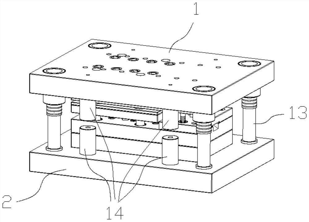
[0027] Such as figure 2 , 3 , as shown in 4:

[0028] A punching die stroke limit device, including a stroke limit device body, the stroke limit device body includes an upper stroke limit column 3 whose upper end is fixedly connected with an upper die base 1, and whose lower end is fixedly connected with a lower die base 2 The lower stroke limit column 5, the limit column stroke detection mechanism, and the limit column stroke protection mechanism, the upper stroke limit column 3 and the lower stroke limit column 5 are arranged coaxially along the longitudinal direction and used in conjunction with each other. The above-mentioned downstroke limit post 5 is respectively connected with the limit post travel detection mechanism and the limit post travel protection mechanism.

[0029] This embodiment provides the most basic structure of the present invention. The closed state of the upper mold base and the lower mold base and whether they are parallel can be detected by the lim...

Embodiment 2

[0031] This embodiment is an improvement made on the basis of Embodiment 1, specifically:

[0032] Such as figure 2 , 3 , as shown in 4:

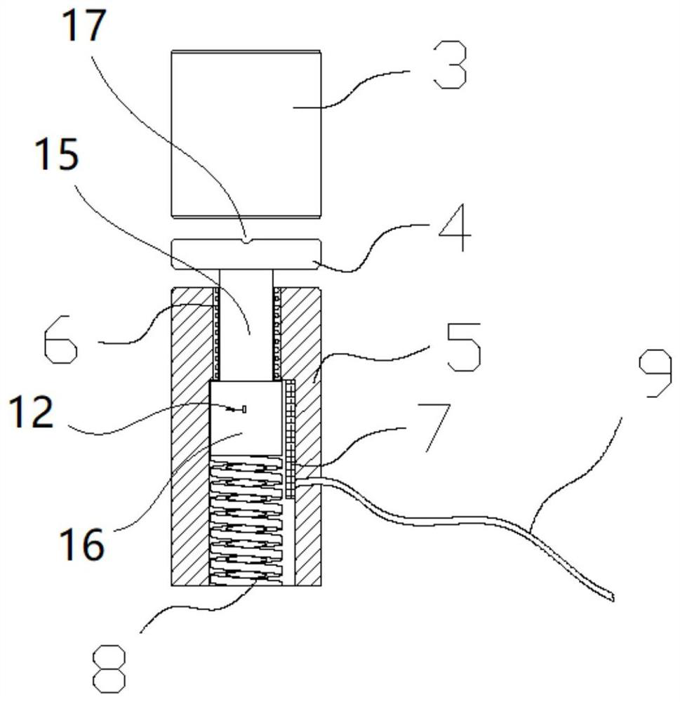
[0033] The top end of the downstroke limiting column 5 is provided with an installation groove extending in the downward stroke limiting column 5 along the axis, and the stroke detection mechanism of the limiting column includes a steel ball guide set coaxially on the upper part in the installation groove. Sleeve 6, sliding rod 15 that is slidably connected to the steel ball guide sleeve 6, fixedly connected to the top of the sliding rod 15 and a detection block 4 located above the downstroke limit post 3, and a limit base 16 that is fixedly connected to the bottom end of the slide rod, set at the limit position The spring 8 below the base, the observation port 18 provided on the installation groove wall where the side wall of the position-limiting base is located, the scale 11 longitudinally arranged on the outer surface of the observat...

Embodiment 3

[0040] This embodiment is an improvement made on the basis of Embodiment 2, specifically:

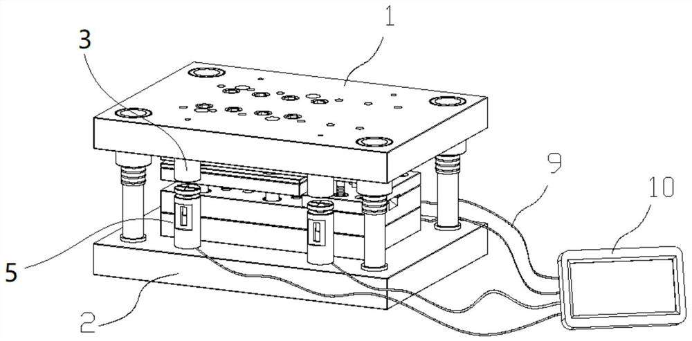
[0041] Such as figure 2 , 3 , 4, the described limiting column stroke protection mechanism includes: a grating ruler 7, a signal line 9, and a display control unit 10 installed on the groove wall of the installation groove below the steel ball guide bush 6, the grating ruler 7 is used to detect the distance that the limit base moves downward. The grating ruler 7 is connected to the display control unit 10 through the signal line 9 penetrating through the wall of the installation groove, and the display control unit 10 transmits the signal detected by the grating ruler 7 displayed on the display screen, and the press is controlled through a preset control program, and the display control unit is electrically connected to the emergency brake control circuit of the press through wires;

[0042] When the grating ruler 7 detects that the pointer mark of the limit base points to the positi...


PUM


Abstract

The invention discloses a stroke limiting device of a blanking die, and relates to the technical field of progressive dies. The device comprises a stroke limiting device body, the stroke limiting device body comprises an upper stroke limiting column with an upper end fixedly connected with an upper die holder, a lower stroke limiting column with a lower end fixedly connected with a lower die holder, a limiting column stroke detection mechanism and a limiting column stroke protection mechanism, the upper stroke limiting column and the lower stroke limiting column are coaxially arranged in the longitudinal direction and used in cooperation with each other, and the lower stroke limiting column is connected with the limiting column stroke detection mechanism and the limiting column stroke protection mechanism. The device can effectively solve the problem that direct measurement cannot be performed when upper and lower dead points of a die are adjusted, sudden stop of the press is controlled through die closing over-travel in the die pressure test and press blanking process, the pressing depth is adjusted again after confirmation, direct closing and damage to the equipment die are avoided, the stamping depth of the die every time is consistent, and the closing height of the die can be directly displayed and read. Secondly, the parallelism of a die holder and a press table top is indirectly confirmed through the height difference value of the multiple limiting columns.

Description

technical field [0001] The invention relates to the technical field of progressive dies, in particular to a stroke limiting device for a blanking die. Background technique [0002] Conventional progressive die stroke limit column 14 such as figure 1 As shown, it is fixed between the upper and lower mold bases through thread and bolt connection, and the installation position and installation quantity are set according to the mold shape length size and precision requirements. Its function is to limit the travel of the upper and lower mold bases. In use, it is necessary to measure the gap at the end of the upper and lower limit posts to determine whether the mold is closed in place, and to ensure that the height of each bottom dead center of the mold stamping is consistent during the stamping process. [0003] However, the above-mentioned travel limit post has the following defects in use: [0004] 1. When changing material strips of different thicknesses or adjusting the bot...

Claims


Application Information

Patent Timeline
Patent Type & Authority Applications(China)
IPC IPC(8): B21D28/14B21D55/00B21C51/00
CPCB21D28/14B21D55/00B21C51/00
Inventor 刘毅杨文逄宁宁金慧吕培晓
Owner 青岛征和链传动有限公司
Why Eureka
Try Eureka