
Compound impact body, impact hydraulic formation equipment and impact hydraulic formation method

A technology of hydroforming and impact body, applied in the field of impact hydroforming equipment and impact hydroforming, composite impact body, can solve the problems of long time consumption, energy loss, complicated operation, etc., to achieve convenient replacement, improve forming performance, reduce energy The effect of loss

Active Publication Date: 2021-08-24
INST OF METAL RESEARCH - CHINESE ACAD OF SCI
View PDF7 Cites 2 Cited by
  • Summary
  • Abstract
  • Description
  • Claims
  • Application Information

AI Technical Summary

Problems solved by technology

[0004] However, the inventors of the present invention have found that the existing impact hydroforming equipment has at least the following technical problems: since the impact power source generating device can only drive a solid impact body for a single impact, if secondary loading is to be performed, the impact body needs to be returned to the ground again. position, and start the impact power source generating device again; this will lead to problems such as cumbersome operation, long time-consuming, low efficiency; more importantly, the energy loss during a single strike is serious

Method used


Image

  • Compound impact body, impact hydraulic formation equipment and impact hydraulic formation method
  • Compound impact body, impact hydraulic formation equipment and impact hydraulic formation method
  • Compound impact body, impact hydraulic formation equipment and impact hydraulic formation method

Examples


Embodiment 1

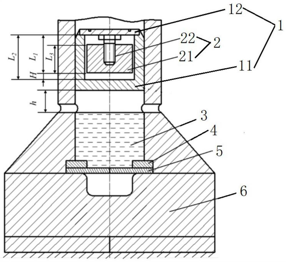
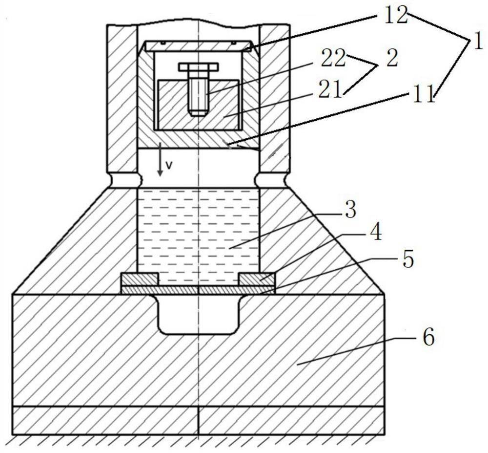
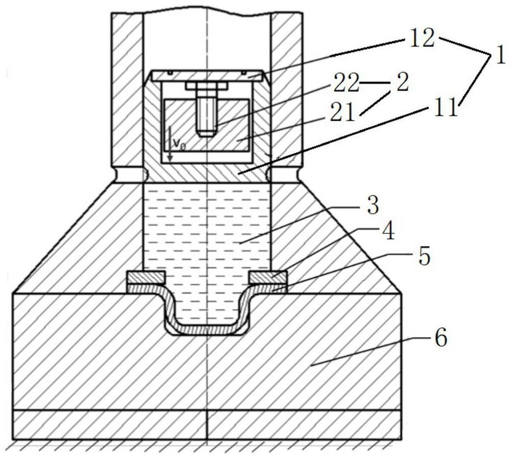
[0054] On the one hand, this embodiment provides a composite impact body for use in impact hydroforming equipment, such as Figure 1 to Figure 4 , Figure 6 to Figure 8 As shown, the composite impact body of this embodiment includes a primary impact structure 1 and a secondary impact structure 2; wherein, the primary impact structure 1 has a closed cavity. The secondary impact structure 2 is located in the closed cavity of the primary impact structure 1, and can move along the impact direction in the closed cavity (it can also move in the opposite direction of the impact direction in the closed cavity, that is, it can move in the closed cavity longitudinal movement in the body). Among them, in the process of impact hydroforming: after the primary energy is released, the composite impact body moves (see figure 2 ), when the primary impact structure 1 touches the liquid surface of the liquid chamber 3 and stops moving, the secondary impact structure 2 can continue to move alo...

Embodiment 2

[0058] Preferably, this embodiment proposes a composite impact body, compared with the previous embodiment, as Figure 1 to Figure 4 , Figure 6 to Figure 8 As shown, the present embodiment further designs the primary impact structure 1 as follows:

[0059] The primary impact structure 1 includes: a primary impact body 11 and a baffle 12 . Wherein, the primary impact body 11 has a groove structure; the baffle plate 12 is connected with the primary impact body 11, and is used to block the notch of the groove structure, so as to form a closed cavity of the primary impact structure 1 with the groove structure. Preferably, the baffle plate 12 is connected to the primary impact body 11 through fasteners, preferably through bolts.

[0060] Here, the composite impact body provided in this embodiment is designed by designing the primary impact structure 1 as a primary impact body 11 with a groove structure and a baffle plate 2 for blocking the notch of the groove structure. Placing...

Embodiment 3

[0062] Preferably, this embodiment proposes a composite impact body, compared with the previous embodiment, as Figure 1 to Figure 4 , Figure 6 to Figure 8 As shown, the present embodiment further designs the secondary impact structure 2 as follows:

[0063] The secondary impact structure 2 comprises a secondary impact body 21 and an adjustment device 22 . Wherein, the adjustment device 22 is connected with the secondary impact body 21, and is used to adjust the longitudinal distance H between the secondary impact structure 2 and the closed cavity (that is, the longitudinal length L of the closed cavity). 2 with the longitudinal length L of the secondary impact structure 1 Difference). Wherein, the longitudinal direction of the secondary impact structure 2 and the closed cavity 1 is parallel to the impact direction; the set distance is equal to the longitudinal separation distance H. Wherein, when the secondary impact structure 2 is in contact with the baffle plate 12 (or...


PUM


Abstract

The invention discloses a compound impact body, impact hydraulic formation equipment and an impact hydraulic formation method. The mainly adopted technical scheme is characterized in that the compound impact body comprises a primary impact structure and a secondary impact structure, wherein the primary impact structure is provided with an enclosed chamber body; the secondary impact structure is positioned in the enclosed chamber body of the primary impact structure and can be moved in the enclosed chamber body in the impact direction; in an impact hydraulic formation process, after one-time energy is released, the compound impact body is moved, the secondary impact structure can continuously move in the enclosed chamber body in the impact direction when the primary impact structure contacts the liquid level of a liquid chamber and then stops moving, the primary impact structure is stroke after the secondary impact structure is moved at a set distance, so that secondary impact loading of blanks under single-time energy release is realized, the energy is fully utilized and energy loss in the impact hydraulic formation process is reduced, and more importantly, the formation performance of materials can be improved under the effect of the compound impact body.

Description

technical field [0001] The invention relates to the technical field of high strain rate forming, in particular to a composite impact body, impact hydroforming equipment and impact hydroforming method. Background technique [0002] Impact hydroforming is a kind of high-strain rate forming technology. Its technical principle is to organically combine hydroforming and impact forming. The high-speed impact body hits the surface of the liquid chamber to generate shock waves, and acts on the blank through the liquid medium to form final artifact. This technology is mainly used in the processing and manufacturing fields of aviation, automobile industry and precision instruments. [0003] The existing impact hydroforming equipment mainly utilizes the impact power source generating device to drive the solid metal impact body to accelerate it to a high strain rate range in an instant. Different impact speeds and impact pressures can be achieved by changing the mass of the solid impa...

Claims


Application Information

Patent Timeline
Patent Type & Authority Applications(China)
IPC IPC(8): B21D22/02B21D37/00B21C51/00
CPCB21D26/021B21D26/027
Inventor 徐勇夏亮亮张士宏陈大勇李昊娄光赫邓泉水
Owner INST OF METAL RESEARCH - CHINESE ACAD OF SCI
Learn More