
Automobile battery liquid cooling heat dissipation device based on steam cavity heat dissipation technology

A technology for liquid cooling and heat dissipation of automobiles, applied to secondary batteries, circuits, electrical components, etc., can solve problems such as poor temperature uniformity and complex structure, and achieve compact layout, high cooling efficiency, and reduced heat transfer resistance Effect

Active Publication Date: 2021-08-20
WUHAN UNIV OF TECH
View PDF18 Cites 1 Cited by
  • Summary
  • Abstract
  • Description
  • Claims
  • Application Information

AI Technical Summary

Problems solved by technology

[0006] The purpose of the present invention is to overcome the problems of complex structure and poor temperature uniformity in the prior art, and to provide a liquid-cooled heat dissipation device for automobile batteries based on steam chamber heat dissipation technology with simple structure, flexible assembly, and good heat dissipation effect

Method used


Image

  • Automobile battery liquid cooling heat dissipation device based on steam cavity heat dissipation technology
  • Automobile battery liquid cooling heat dissipation device based on steam cavity heat dissipation technology
  • Automobile battery liquid cooling heat dissipation device based on steam cavity heat dissipation technology

Examples


Embodiment 1

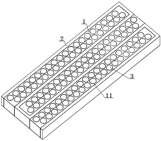
[0047] A car battery liquid cooling heat dissipation device based on steam chamber heat dissipation technology, the liquid cooling heat dissipation device includes: a heat conduction steam chamber 1, a liquid cooling channel 2 and a plurality of power batteries 3, and the liquid cooling channel 2 is curved in a reverse direction structure, a heat conduction steam chamber 1 closely attached to the bending area of ​​the liquid cooling channel 2 is provided, and a plurality of battery installation grooves 11 are arranged on the heat conduction steam chamber 1, and a single battery battery installation groove 11 is fixed with A power battery 3; the heat conduction steam chamber 1 is a vacuum steam chamber filled with pure water and provided with a capillary core structure; the power battery 3 is fixed in the battery installation groove 11 through thermal conductive glue or graphite sheet; the liquid cooling The channel 2 includes at least two cooling horizontal pipes 21 arranged in...

Embodiment 2

[0049] Embodiment 2 is basically the same as Embodiment 1, and its difference is:

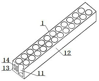
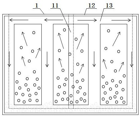
[0050] The heat conduction steam chamber 1 includes: a heat conduction shell 12, a heat conduction capillary core 13, the inner wall of the heat conduction shell 12 is provided with a heat conduction capillary core 13 connected with it as a whole, and the middle part of the heat conduction capillary core 13 is along the heat conduction steam chamber 1 At least one steam cavity 14 is opened in the direction of the central axis; one to two rows of battery installation grooves 11 are opened on the heat conduction housing 12, and the top of the battery installation grooves 11 is sealed and connected with the top plate of the heat conduction housing 12, so The groove wall of the battery installation groove 11 is a sealed structure, and the groove wall of the battery installation groove 11 is in close contact with the heat conduction capillary core 13 at the corresponding position inside the heat cond...

Embodiment 3

[0052] Embodiment 3 is basically the same as Embodiment 2, and its difference is:

[0053] The middle part of the heat-conducting capillary wick 13 is provided with three parallel steam cavities 14 along the central axis of the heat-conducting steam cavity 1 , wherein the steam cavity in the middle has a larger cross-sectional area than the rest of the steam cavities.


PUM

PropertyMeasurementUnit
diameteraaaaaaaaaa
pore sizeaaaaaaaaaa

Abstract

An automobile battery liquid cooling heat dissipation device based on a steam cavity heat dissipation technology comprises a heat conduction steam cavity, a liquid cooling channel and a plurality of power batteries, the liquid cooling channel is of a return bending structure, the heat conduction steam cavity tightly attached to the liquid cooling channel is arranged between bending areas of the liquid cooling channel, a plurality of battery mounting grooves are formed in the heat conduction steam cavity, and a power battery is fixed in each battery mounting groove. According to the design, the steam cavity structure is adopted for heat transfer, the steam cavity structure is good in heat dissipation performance, flexible, simple and convenient, local heat generated by the battery pack module can be rapidly taken away, high effective heat dissipation of an electric vehicle battery under the high heat flux density is achieved, meanwhile, uniform temperature distribution is kept in the running process, and the service life and the cruising ability of the automobile battery are prolonged.

Description

technical field [0001] The invention relates to a liquid-cooled heat dissipation device for an automobile battery based on the heat dissipation technology of a steam cavity, and is particularly suitable for improving the heat dissipation efficiency of an automobile power battery pack. Background technique [0002] In recent years, with the rapid development of industry, the automobile industry has consumed a huge amount of fossil energy, and has also brought serious environmental pollution problems. By improving the oil supply system and exhaust gas purification technology, the effect of controlling energy consumption and environmental pollution is not significant. New energy vehicles, especially pure electric vehicles, are favored by governments and automobile companies of various countries because of their advantages of energy saving and almost zero emission of vehicle exhaust. In order to promote my country's energy conservation and ecological civilization construction, ...

Claims


Application Information

Patent Timeline
Patent Type & Authority Applications(China)
IPC IPC(8): H01M10/613H01M10/617H01M10/625H01M10/643H01M10/653H01M10/6556H01M10/6567H01M10/6568H01M10/6569
CPCH01M10/613H01M10/617H01M10/625H01M10/643H01M10/653H01M10/6556H01M10/6567H01M10/6568H01M10/6569Y02E60/10
Inventor 明廷臻李澳铖吴永佳石天豪陈森
Owner WUHAN UNIV OF TECH
Learn More