Thermal compensation method for combustion chamber of rapid compressor

A combustion chamber and compressor technology, which is applied in mechanical equipment, machines/engines, liquid variable displacement machinery, etc., can solve problems such as unavoidable heat dissipation, temperature and pressure drop in the combustion chamber, and differences in the degree of influence by heat loss.

Active Publication Date: 2021-08-20
XI AN JIAOTONG UNIV
View PDF6 Cites 2 Cited by
  • Summary
  • Abstract
  • Description
  • Claims
  • Application Information

AI Technical Summary

Problems solved by technology

However, due to the inevitable heat dissipation in actual use, usually when the piston stops moving, the temperature and pressure in the combustion chamber will begin to drop
Due to different geometric structures and operating parameters of different fast compressor test benches, the degree to which the experimental process is affected by heat loss is also significantly different. The development of the model adversely affects the

Method used


Image

  • Thermal compensation method for combustion chamber of rapid compressor
  • Thermal compensation method for combustion chamber of rapid compressor
  • Thermal compensation method for combustion chamber of rapid compressor

Examples


Embodiment Construction

[0048] The present invention will be further described in detail below in conjunction with the accompanying drawings, which are explanations rather than limitations of the present invention.

[0049] refer to Figure 1-6 , a method for fast compressor combustion chamber heat compensation, comprising the following steps:

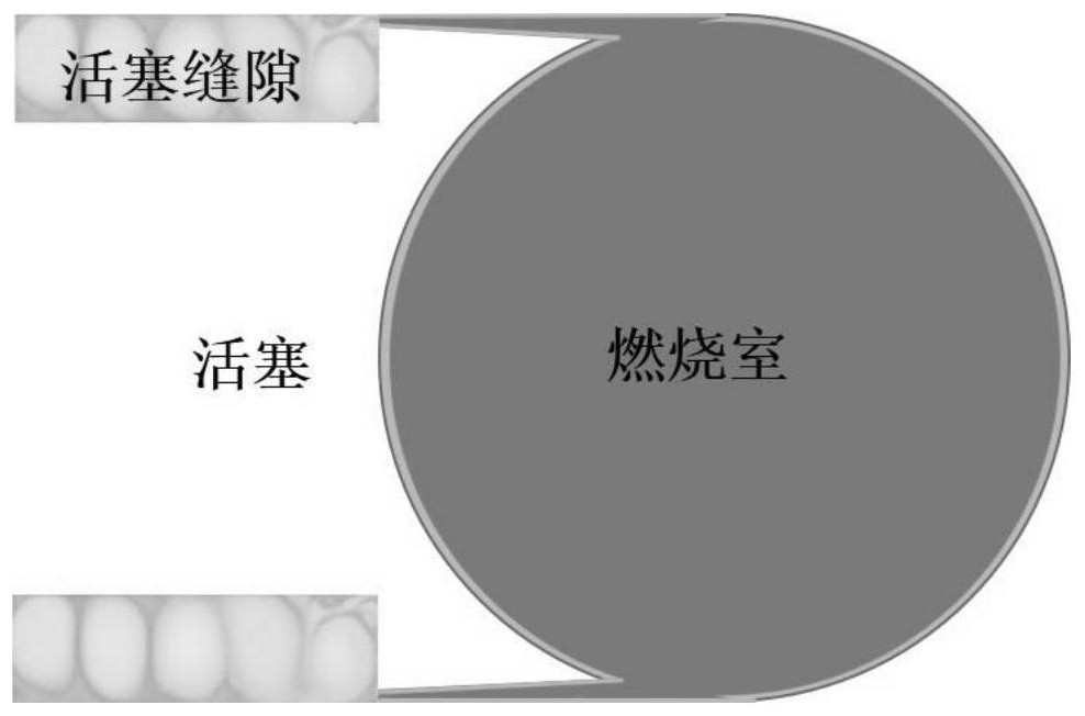
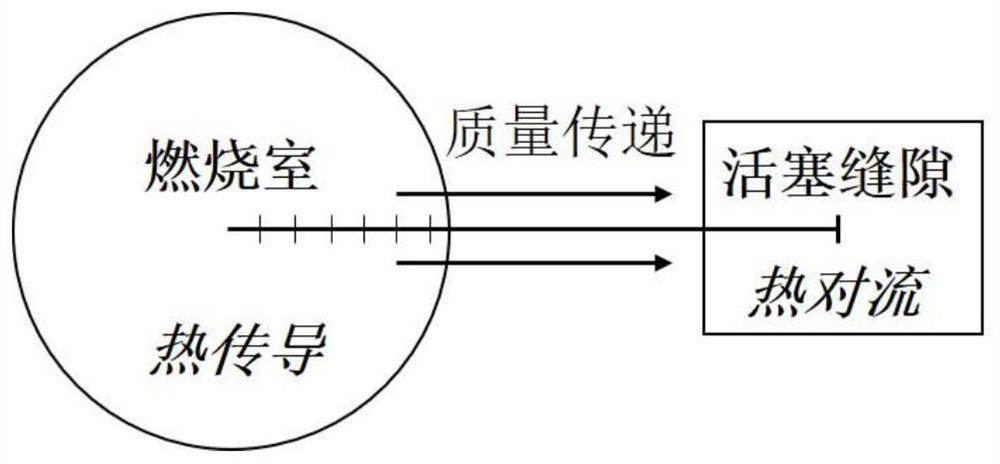
[0050] Step 1. Establish a heat dissipation model of the fast compressor. The calculation domain of the heat dissipation model includes the combustion chamber and the gap between the side wall of the combustion chamber and the piston.

[0051] The combustion chamber of the fast compressor communicates with the gap between the piston and the compression cylinder wall. The piston gap contains the boundary layer gas in the volume swept by the piston during the compression process, suppresses the vortex generated by the high-speed movement of the piston, and increases the temperature in the combustion chamber. Uniformity.

[0052] The gap formed due to the deform...


PUM


Abstract

According to a thermal compensation method for a combustion chamber of a rapid compressor disclosed by the invention, under the condition of no thermal compensation, the heat dissipation model is used for obtaining a predicted value of a pressure decline curve caused by heat dissipation and mass transfer of the combustion chamber within a set time range, and the predicted value of the model is compared with a pressure curve measured value obtained by an experiment; model prediction and experimental measurement results are made to be the same by adjusting heat exchange coefficients, the number of calculation units and time steps of combustion chamber calculation units in the heat dissipation model, then adjusted parameters are input into the model to operate under the thermal compensation condition, and a piston motion curve needed by thermal compensation under the working condition is obtained. The piston movement speed of the rapid compressor is controlled according to the obtained piston movement speed curve, and the purpose of heat dissipating capacity compensation of a core area of a combustion chamber is achieved; according to the method, the heat loss of the combustion chamber of the rapid compressor is reduced, the maintaining time of a high-temperature and high-pressure environment is prolonged, and a more ideal thermodynamic environment is provided for research of the fuel oxidation ignition dynamics process.

Description

technical field [0001] The invention relates to the technical field of a rapid compressor for a combustion chemical reaction kinetics experimental device, in particular to a method for thermal compensation of a combustion chamber of a rapid compressor. Background technique [0002] The rapid compressor drives the rapid compression of the piston to rapidly reduce the volume of the combustion chamber, thereby realizing the rapid loading of the high-temperature and high-pressure thermodynamic environment in the combustion chamber, which can be used to test the autoignition and oxidative decomposition characteristics of fuels at specific temperatures and pressures. However, due to the inevitable heat dissipation in actual use, usually when the piston stops moving, the temperature and pressure in the combustion chamber will begin to drop. Due to different geometric structures and operating parameters of different fast compressor test benches, the degree to which the experimental ...

Claims


Application Information

Patent Timeline
Patent Type & Authority Applications(China)
IPC IPC(8): G06F30/20G06F30/28G16C20/10F04B49/06F04B49/20G06F119/14G06F119/08
CPCG06F30/20G06F30/28G16C20/10F04B49/065F04B49/20G06F2119/14G06F2119/08
Inventor 武颖韬刘传胜汤成龙黄佐华
Owner XI AN JIAOTONG UNIV
Why Eureka
Try Eureka