
An aoi vision test system for scratch detection of mobile phone wireless charging base

A mobile phone wireless charging and testing system technology, applied in the field of AOI visual testing system for mobile phone wireless charging base scratch detection, can solve the problems of inconvenient automatic cutting, inconvenient automatic flip detection, etc., and achieve the effect of improving efficiency

Active Publication Date: 2022-12-02
昆山宸泽测控科技有限公司
View PDF11 Cites 0 Cited by
  • Summary
  • Abstract
  • Description
  • Claims
  • Application Information

AI Technical Summary

Problems solved by technology

[0005] Aiming at the deficiencies of the prior art, the present invention provides an AOI visual testing system for scratch detection of mobile phone wireless charging bases, which solves the inconvenience of automatic flip detection when the existing AOI visual testing equipment detects the charging base, And the problem of inconvenient automatic feeding after detection

Method used


Image

  • An aoi vision test system for scratch detection of mobile phone wireless charging base
  • An aoi vision test system for scratch detection of mobile phone wireless charging base
  • An aoi vision test system for scratch detection of mobile phone wireless charging base

Examples


Embodiment 1

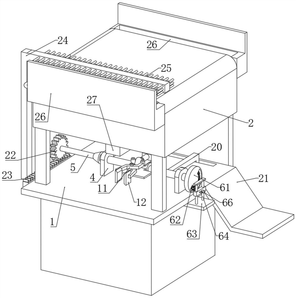
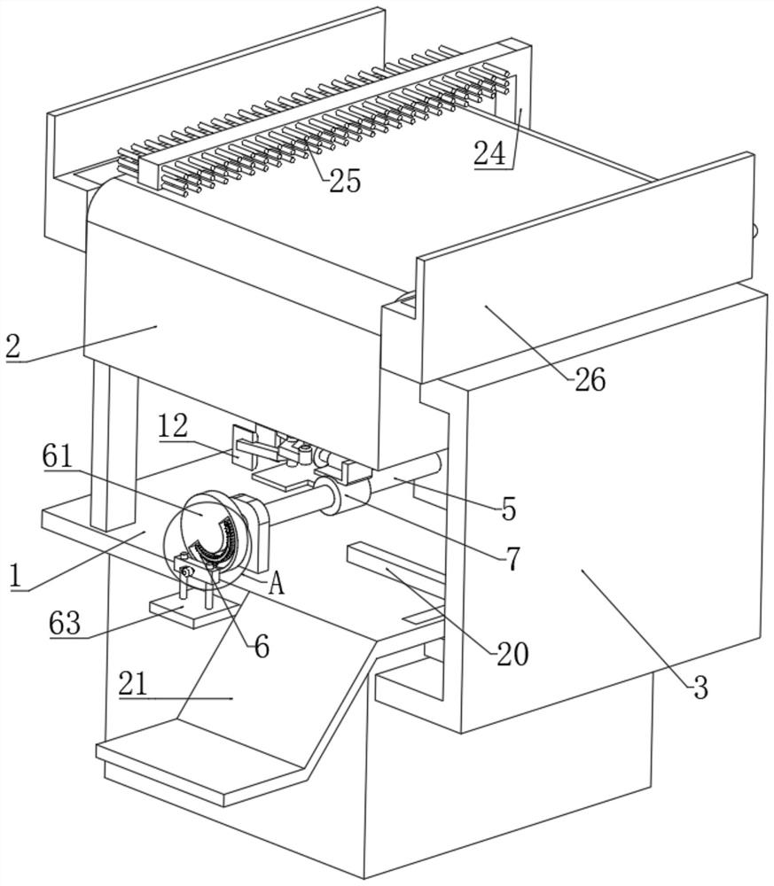
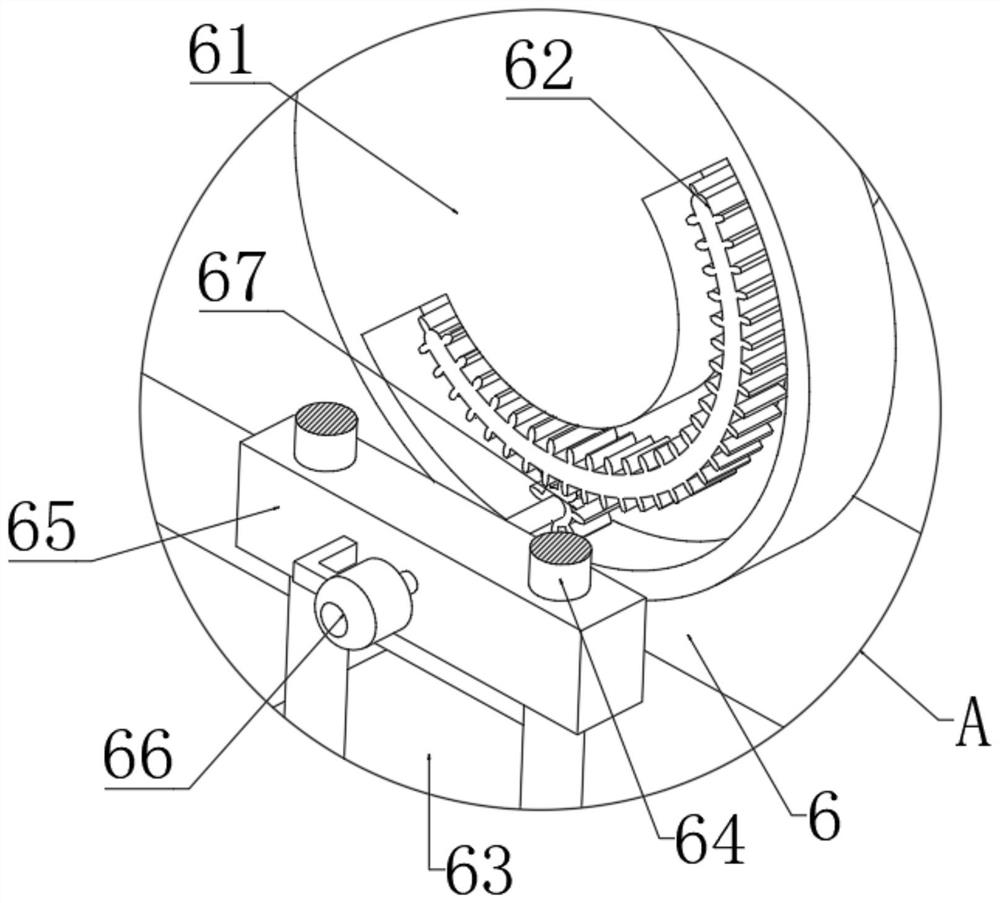
[0025]Embodiment 1: An AOI visual test system for scratch detection of mobile phone wireless charging base, including a workbench 1 and a detection device 2, a display screen 3 is installed on the rear end of the detection device 2, and the display screen 3 and the detection device 2 Electrical connection, the upper end surface of the workbench 1 is symmetrically fixedly connected with the boss 4, and the support shaft 5 is connected with the support shaft 5 through the rotation between the bosses 4, the right end of the support shaft 5 is provided with a reciprocating mechanism 6, and the outer wall of the support shaft 5 is fixed Connected with a fixed sleeve 7, the upper end surface of the fixed sleeve 7 is fixedly connected with the electric telescopic rod 8 through the mounting plate, the front end surface of the fixed sleeve 7 is fixedly connected with the support plate 10, and the upper end surface of the support plate 10 is connected with scissors through the symmetrical...

Embodiment 2

[0026] Embodiment 2: The difference between this embodiment and Embodiment 1 is that the outer wall of the support shaft 5 is fixedly connected with the first bevel gear 14, and the upper end surface of the workbench 1 is connected with the transmission shaft 16 through the convex plate 17, and the transmission shaft 16 The front end surface is fixedly connected with the second bevel gear 15, the first bevel gear 14 is meshed with the second bevel gear 15, the right end of the transmission shaft 16 is fixedly connected with the first gear 18, and the lower end surface of the workbench 1 is slidably connected with the first gear Bar 19, the first gear 18 is meshed with the first rack 19, the upper end surface of the workbench 1 is slidably connected with a push plate 20 through the chute, and one end of the push plate 20 penetrating the chute is fixedly connected with the first rack 19, supporting The left end of the shaft 5 is fixedly connected with a second gear 22, the left s...


PUM


Abstract

The invention discloses an AOI visual testing system for detecting scratches on a mobile phone wireless charging base, which includes a workbench and testing equipment. A display screen is installed on the rear end of the testing equipment, and the display screen is electrically connected to the testing equipment. , the upper end surface of the workbench is symmetrically and fixedly connected with a boss, and a support shaft is connected through the rotation between the bosses, and a cylinder is fixedly connected to one end of the two scissor frames close to the tapered block, and the scissor frame One end away from the tapered block is fixedly connected with a clamping pad, the lower end surface of the detection device is equipped with a detection head, and the right side wall of the workbench is fixedly connected with a guide plate. The present invention relates to the technical field of AOI visual detection equipment. The AOI visual testing system for scratch detection of mobile phone wireless charging base solves the problem that the existing AOI visual inspection equipment is inconvenient to conduct a comprehensive inspection when detecting the charging base, and it is inconvenient to automatically unload the material after detection.

Description

technical field [0001] The invention relates to the technical field of AOI visual inspection equipment, in particular to an AOI visual inspection system for scratch detection on a mobile phone wireless charging base. Background technique [0002] The wireless charger is a device that uses the principle of electromagnetic induction for charging. Its principle is similar to that of a transformer. By placing a coil at the sending and receiving ends, the coil at the sending end sends an electromagnetic signal to the outside under the action of electricity, and the coil at the receiving end receives the electromagnetic signal. Signal and convert the electromagnetic signal into electric current, so as to achieve the purpose of wireless charging. The wireless charging base needs to use AOI automatic optical inspection equipment to detect whether there are scratches on the outer wall of the base during processing. AOI testing equipment is based on optical principles to detect commo...

Claims


Application Information

Patent Timeline
Patent Type & Authority Patents(China)
IPC IPC(8): G01N21/15G01N21/01G01N21/88
CPCG01N21/15G01N21/01G01N21/88G01N2021/152G01N2021/0112
Inventor 李健毛订订李志伟
Owner 昆山宸泽测控科技有限公司
Learn More