
Design method of sinking headframe for vertical shaft expanding excavation

A design method and well-sinking technology, which can be used in vertical shaft equipment, drilling equipment, mining equipment, etc., can solve problems such as non-reuse, inability to perform overall translation operations, and distortion of tubular derricks, so as to reduce the floor space and increase the daily The effect of maintenance, inspection and repair work and reducing the space occupied

Pending Publication Date: 2021-08-20
BEIJING CHINA COAL MINE ENG CO LTD +1
View PDF0 Cites 1 Cited by
  • Summary
  • Abstract
  • Description
  • Claims
  • Application Information

AI Technical Summary

Problems solved by technology

[0003] The derricks in the prior art are all permanent tubular derricks in coal mines. The permanent derricks are connected by short steel pipes with flange bolts. The installation accuracy is high, but the overall translation operation cannot be performed.
If the parallel operation is forced, the tubular derrick will be twisted, and even if it is moved, it cannot be used again
[0004] Therefore, the existing permanent tubular derrick is completely unsuitable for use in the process of shaft expansion and sinking. The vertical shaft expansion and sinking derrick needs to be moved after the construction of the shaft is completed, so it is required to be light in weight and not deformed during the movement. use again

Method used


Image

  • Design method of sinking headframe for vertical shaft expanding excavation
  • Design method of sinking headframe for vertical shaft expanding excavation
  • Design method of sinking headframe for vertical shaft expanding excavation

Examples


Embodiment Construction

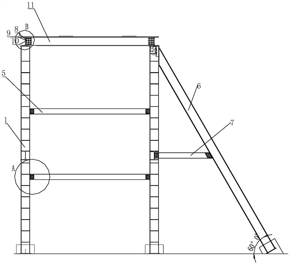
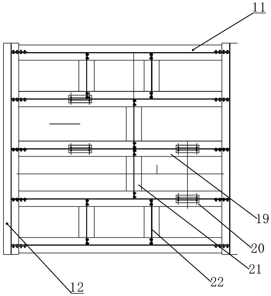
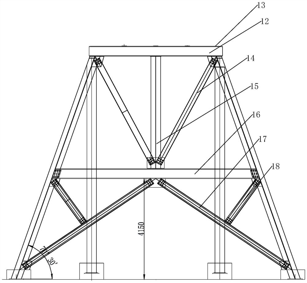
[0130] The new type of vertical shaft expansion and sinking derrick is designed to meet the type of shaft construction operations of vertical shaft brushing and lower horizontal gangue. Supported by integral steel frame. The force is uniform and reasonable, and the plane and three-dimensional space are saved.

[0131] 1. Construction background

[0132] The Yili River IV Hydropower Station is located in the downstream Jinsha River Baihetan Hydropower Station reservoir area. The hydropower station hub consists of the first hub building and the water diversion power generation system building. After the Baihetan Hydropower Station stores water to generate electricity, the backwater of the reservoir will submerge the tail water system, underground powerhouse and part of the water diversion tunnel of the Yili River IV Hydropower Station. recovery.

[0133] The ground outlet field is located in the gentle slope of Dapingzi on the east side of the underground factory building, cl...


PUM


Abstract

The invention discloses a design method of a sinking headframe for vertical shaft expanding excavation. The design method comprises the following steps: (1) performing structural design of the sinking headframe for vertical shaft expanding excavation; (2) selecting a structural material of the sinking headframe for vertical shaft expanding excavation; and (3) verifying the load and strength of the sinking headframe for vertical shaft expanding excavation. A bearing main beam is designed into a single piece of integral high-strength section steel, and the integral hoisting and translation work of the headframe can be completely completed through calculation. The sinking headframe for vertical shaft expanding excavation does not need a waste rock discharging and turning operation system, suspension arrangement is simple, the shaft construction headframe of the type does not need full-section area coverage of a shaft, only a base span of the headframe and a head sheave platform coverage range need to be arranged and designed according to in-well suspension equipment, and the occupied area and the occupied space of the novel headframe are further reduced. The novel headframe can be suitable for single-side lifting suspension arrangement, inclined supports are made of single pieces of integral overall high-strength section steel, stress is even, release of acting force and counter-acting force is even, and the stress state of the novel headframe cannot be affected.

Description

technical field [0001] The invention relates to the technical field of mine head frame design. Specifically, the utility model relates to a design method for a vertical shaft expansion and sinking derrick. Background technique [0002] The derrick is a device used to place the crown block, hang traveling blocks, hooks, rings, elevators and other equipment during drilling or workover, and to lift and store drill pipes, oil pipes and sucker rods. [0003] The derricks in the prior art are all permanent tubular derricks in coal mines. The permanent derricks are connected by short steel pipe flange bolts, and the installation accuracy is high, but they cannot be translated as a whole. If the parallel operation is forced, the tubular derrick will be twisted, and even if it is moved, it cannot be used again. [0004] Therefore, the existing permanent tubular derrick is completely unsuitable for use in the process of shaft expansion and sinking. The vertical shaft expansion and s...

Claims


Application Information

Patent Timeline
Patent Type & Authority Applications(China)
IPC IPC(8): E21B15/00E21D7/00G06F30/13G06F119/14
CPCE21B15/00E21B15/006E21D7/00G06F30/13G06F2119/14
Inventor 许峰胡传安刘志强秦政程守业董之村周武李功子于见水李俊峰
Owner BEIJING CHINA COAL MINE ENG CO LTD
Learn More