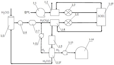
A high-safety fuel cell electrolyzer system and its working method
A fuel cell, high-safety technology, applied in the field of electrolysis cells, can solve the problems of low efficiency of SOEC system, low utilization rate of water vapor, inconvenient use, etc. Effect
- Summary
- Abstract
- Description
- Claims
- Application Information
AI Technical Summary
Problems solved by technology
Method used
Image
Examples
no. 1 Embodiment approach
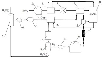
[0035]as attached figure 2 As shown, a high-safety fuel cell electrolyzer system includes: fan 1, air heat exchanger 2, electric heater 3, air-gas heat exchanger 4, water tank 5, water pump 6, steam generator 7, gas Heat exchanger 8, mixer 9, SOEC stack 10, condenser 11, water-gas separator 12, booster pump 13, high-pressure gas cylinder 14, flow meter 15.
[0036] The blower 1, the air heat exchanger 2, the electric heater 3, and the air-gas heat exchanger 4 are connected in sequence to form a supply flow path on the cathode side. The fan 1 is used to compress the air and send it to the air heat exchanger 2; the air heat exchanger 2 is used to send the air sent by the fan 1 and the high-temperature cathode tail gas discharged from the SOEC stack 10 heat exchange; the electric heater 3 is used to heat the air; the air-gas heat exchanger 4 is used to exchange heat between the high-temperature air heated by the electric heater 3 and the water vapor on the anode side. The abov...
no. 2 Embodiment approach
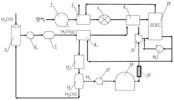
[0044] as attached image 3 As shown, a high-safety fuel cell electrolyzer system includes: fan 1, air heat exchanger 2, electric heater 3, air-gas heat exchanger 4, water tank 5, water pump 6, steam generator 7, gas Heat exchanger 8, mixer 9, SOEC stack 10, condenser 11, water-gas separator 12, booster pump 13, high-pressure gas cylinder 14, flow meter 15, high-temperature circulation pump 16.
[0045] The blower 1, the air heat exchanger 2, the electric heater 3, and the air-gas heat exchanger 4 are connected in sequence to form a supply flow path on the cathode side. The fan 1 is used to compress the air and send it to the air heat exchanger 2; the air heat exchanger 2 is used to send the air sent by the fan 1 and the high-temperature cathode tail gas discharged from the SOEC stack 10 heat exchange; the electric heater 3 is used to heat the air; the air-gas heat exchanger 4 is used to exchange heat between the high-temperature air heated by the electric heater 3 and the wa...
no. 3 Embodiment approach
[0055] as attached Figure 4 As shown, a high-safety fuel cell electrolyzer system includes: fan 1, air heat exchanger 2, electric heater 3, air-gas heat exchanger 4, water tank 5, water pump 6, steam generator 7, gas Heat exchanger 8, ejector 17, SOEC stack 10, condenser 11, water-gas separator 12, booster pump 13, high-pressure gas cylinder 14, flow meter 15, valve 18.
[0056] The blower 1, the air heat exchanger 2, the electric heater 3, and the air-gas heat exchanger 4 are connected in sequence to form a supply flow path on the cathode side. The fan 1 is used to compress the air and send it to the air heat exchanger 2; the air heat exchanger 2 is used to send the air sent by the fan 1 and the high-temperature cathode tail gas discharged from the SOEC stack 10 heat exchange; the electric heater 3 is used to heat the air; the air-gas heat exchanger 4 is used to exchange heat between the high-temperature air heated by the electric heater 3 and the water vapor on the anode s...
PUM
 Abstract
Description
Claims
Application Information
 - Generate Ideas
- Intellectual Property
- Life Sciences
- Materials
- Tech Scout
- Unparalleled Data Quality
- Higher Quality Content
- 60% Fewer Hallucinations
Browse by: Latest US Patents, China's latest patents, Technical Efficacy Thesaurus, Application Domain, Technology Topic, Popular Technical Reports.
© 2025 PatSnap. All rights reserved.Legal|Privacy policy|Modern Slavery Act Transparency Statement|Sitemap|About US| Contact US: help@patsnap.com


