
Forming box mechanism for 3DP printing technology

A molding box and molding machine technology, applied in 3D object support structures, accessories for processing main materials, additive manufacturing, etc., can solve the problems of wasting printed materials, excessive labor and energy, and being easily affected by environmental factors

Pending Publication Date: 2021-08-20
维捷(苏州)三维打印有限公司
View PDF0 Cites 0 Cited by
  • Summary
  • Abstract
  • Description
  • Claims
  • Application Information

AI Technical Summary

Problems solved by technology

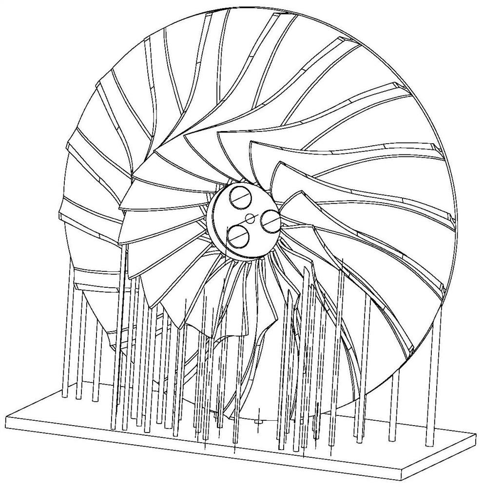
[0002] The method often used in 3DP printing technology is to add some supporting structures around the parts on a flat plate to prevent the deformation and fracture of the parts, such as figure 1 As shown, a part is supported by a number of small cylinders with the bottom facing up, so as to ensure the integrity of the size and structure of the part. This method is easily affected by environmental factors, and too many parts are supported, which wastes the printing material and will cause problems in the later stage. It takes a lot of labor and energy to clean the support. The accuracy of this process is relatively poor, and it is not suitable for industrial-grade production printing. From the perspective of printing safety, the printing machine is damaged because there are no reasonable protection measures for printing. In addition, There is a printing method called 3DPP printing, which is the three-dimensional inkjet printing method. The printing principle is: the 3DP printing machine first lays a layer of printing material on the platform, and then the printing head sprays the material to make the material solidify.

Method used


Image

  • Forming box mechanism for 3DP printing technology
  • Forming box mechanism for 3DP printing technology
  • Forming box mechanism for 3DP printing technology

Examples


Embodiment Construction

[0016] The preferred embodiments of the present invention will be described in detail below in conjunction with the accompanying drawings, so that the advantages and features of the invention can be more easily understood by those skilled in the art, so as to define the protection scope of the present invention more clearly.

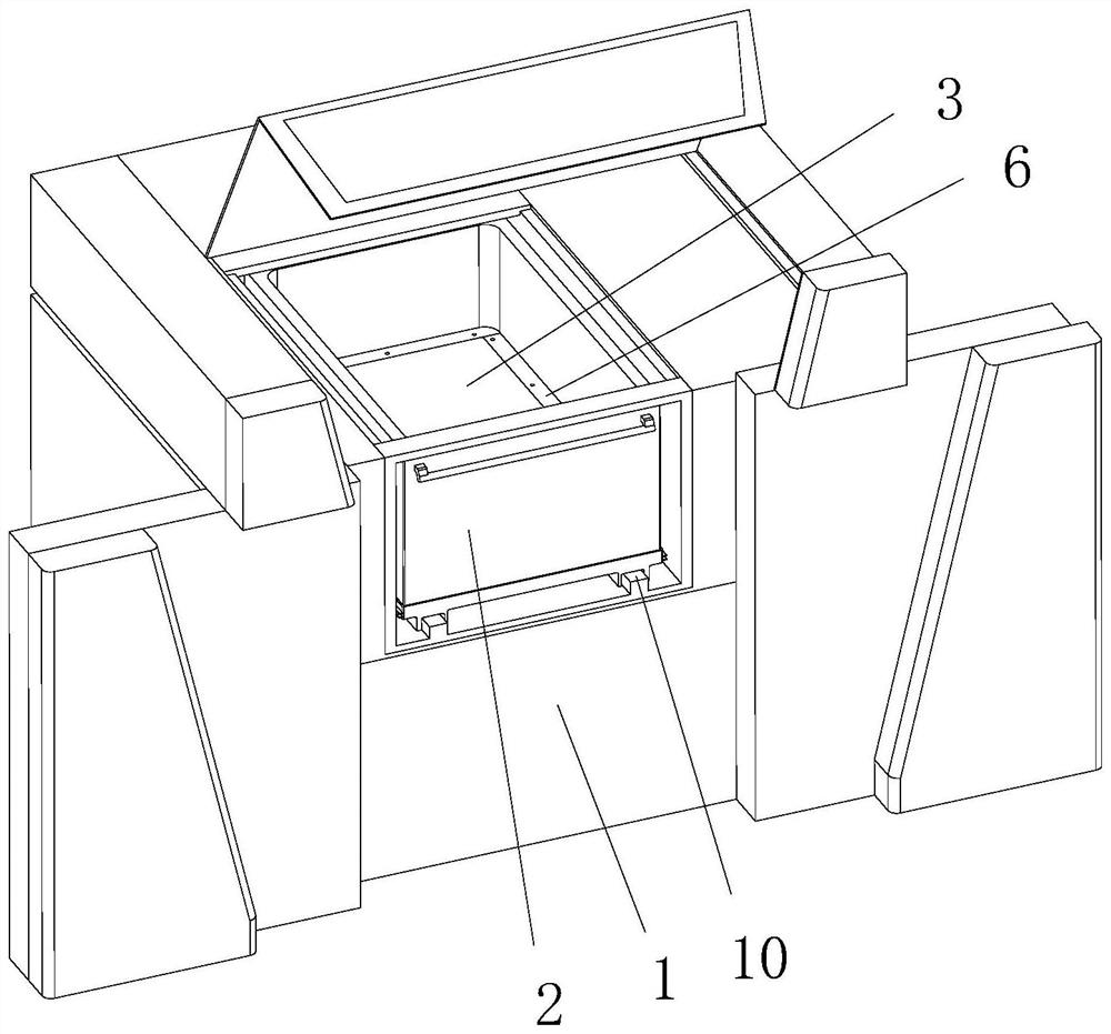
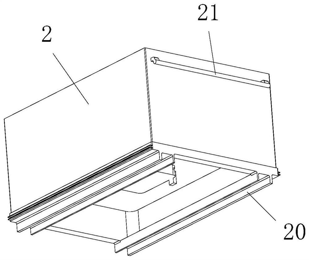
[0017] see Figure 1 to Figure 4 , the embodiment of the present invention includes:

[0018] A forming box mechanism for 3DP printing technology, the forming box mechanism for 3DP printing technology includes a forming frame 1, a forming box body 2, a forming platform 3, a jacking assembly 4, a sealing sponge 5 and a sealing platen 6 , the molding box 2 is slidably inserted on the workbench of the molding frame 1, and the molding platform 3 is housed in the molding box 2, and the molding platform 3 is driven by the jacking assembly 4 to move up and down in the molding box 2, so Sealing grooves are provided around the upper plane of the forming platform...


PUM


Abstract

The invention discloses a forming box mechanism for a 3DP printing technology. The forming box mechanism for the 3DP printing technology comprises a forming rack, a forming box body, a forming platform, a jacking assembly, a sealing sponge and a sealing pressing plate, the forming box body is slidably inserted into a workbench of the forming rack, the forming platform is arranged in the forming box body, the forming platform is driven by the jacking assembly to move up and down in the forming box body, a sealing groove is formed in the periphery of the upper plane of the forming platform, the sealing sponge is arranged on the sealing groove, the sealing pressing plate for packaging the sealing sponge is arranged on the forming platform, and the sealing sponge is tightly attached to the inner wall of the forming box body. By means of the mode, the forming box mechanism for the 3DP printing technology is compact in structure and ingenious in design, supports products in the layer-by-layer printing process, cancels small cylinder supports on original products, achieves efficient utilization of printing materials, avoids waste of the printing materials, and guarantees printing precision and printing stability.

Description

technical field [0001] The invention relates to the field of sand mold 3DP printing technology, in particular to a forming box mechanism for 3DP printing technology. Background technique [0002] The method often used in 3DP printing technology is to add some supporting structures around the parts on a flat plate to prevent the deformation and fracture of the parts, such as figure 1 As shown, a part is supported by a number of small cylinders with the bottom facing up, so as to ensure the integrity of the size and structure of the part. This method is easily affected by environmental factors, and too many parts are supported, which wastes the printing material and will cause problems in the later stage. It takes a lot of labor and energy to clean the support. The accuracy of this process is relatively poor, and it is not suitable for industrial-grade production printing. From the perspective of printing safety, the printing machine is damaged because there are no reasonable ...

Claims


Application Information

Patent Timeline
IPC IPC(8): B29C64/232B29C64/245B29C64/255B33Y30/00
CPCB33Y30/00B29C64/232B29C64/245B29C64/255
Inventor 杨洋黄堪进
Owner 维捷(苏州)三维打印有限公司
Learn More