
Automatic electric arc welding equipment and welding method

A technology of arc welding equipment and welding unit, which is applied in arc welding equipment, welding equipment, welding accessories, etc., can solve the problems of arc light and smoke gas, human injury, troublesome operation process, and high requirements for operators' operation skills, etc., and achieves improvement The effect of welding construction efficiency, reducing work intensity and overcoming quality defects

Pending Publication Date: 2021-08-20
SANJIANG UNIVERSITY
View PDF0 Cites 4 Cited by
  • Summary
  • Abstract
  • Description
  • Claims
  • Application Information

AI Technical Summary

Problems solved by technology

The operation principle of arc welding is not complicated, but it requires high operation skills of the operator. The key in the welding process is how to control the forward direction, angle, feed speed and swing path of the electrode; the welding quality depends on the operator's Technical level, to complete high-quality arc welding requires the operator to have superb welding skills, which can only be achieved after a long period of operation accumulation
Moreover, the operating environment temperature of arc welding is relatively high, and the working environment is poor. Operators who have been engaged in arc welding work for a long time have more or less damage to their waists, arms, wrists and other parts; Smoke, dust, gas, etc. are also harmful to the human body.
Traditional manual arc welding cannot achieve continuous operation. After welding a welding rod, you need to stop and replace the welding rod before continuing to operate. The operation process is cumbersome and the work efficiency is low.

Method used


Image

  • Automatic electric arc welding equipment and welding method
  • Automatic electric arc welding equipment and welding method
  • Automatic electric arc welding equipment and welding method

Examples


Embodiment Construction

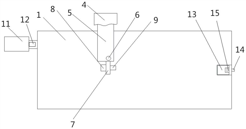
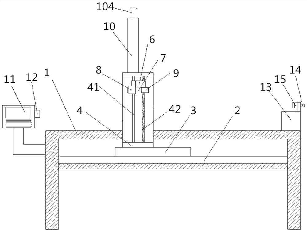
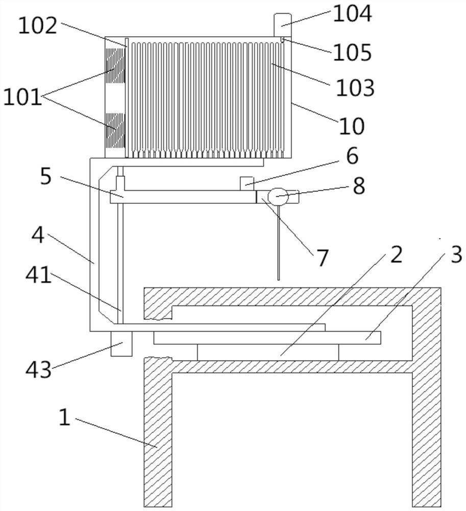
[0028] The present invention will be further described below in conjunction with the accompanying drawings and specific embodiments, but the protection scope of the present invention is not limited thereto.

[0029] In the description of the present invention, it should be understood that the orientation or positional relationship indicated by the terms "upper", "lower", "front", "rear", "left", "right" etc. is based on the orientation shown in the drawings or positional relationship, is only for the convenience of describing the present invention, and does not indicate or imply that the device or element referred to must have a specific orientation, be constructed and operated in a specific orientation, because it cannot be construed as a limitation of the present invention; the term "installation" , "connection", etc. should be understood in a broad sense. For example, it can be a fixed connection, a detachable connection, or an integrated connection, which can be directly co...


PUM


Abstract

The invention provides automatic electric arc welding equipment and a welding method and belongs to the technical field of welding equipment. A first transmission unit, a second transmission unit and a fixed support which are sequentially connected are installed on a workbench of the welding equipment; an electrode holder connecting arm with an electrode holder is installed on the fixed support, a welding rod clamp is installed on the electrode holder, and a welding rod box is installed on the fixed support at the corresponding position above the welding rod clamp; and the first transmission unit, the second transmission unit, the fixed support, the electrode holder and the welding rod clamp all achieve angle adjustment of a welding rod and position adjustment in three directions through matched movement of motors, lead screws and guide rails. According to the whole welding equipment, general control is achieved through a control box, the control box can control the corresponding motors to work and conduct automatic welding by inputting programmed parameters and instructions by an operator, the advancing direction, the angle, the feeding speed and the swing path of the welding rod can be accurately controlled, the welding efficiency and quality are improved, and the working intensity of the operator is reduced.

Description

technical field [0001] The invention belongs to the technical field of welding equipment, and in particular relates to an automatic arc welding equipment and a welding method. Background technique [0002] Arc welding is a welding method widely used in the field of metal processing. The current arc welding operation still uses manual welding. The operation principle of arc welding is not complicated, but it requires high operation skills of the operator. The key in the welding process is how to control the forward direction, angle, feed speed and swing path of the electrode; the welding quality depends on the operator's Technical level, to complete high-quality arc welding requires the operator to have superb welding skills, which can only be achieved after a long period of operation accumulation. Moreover, the operating environment temperature of arc welding is relatively high, and the working environment is poor. Operators who have been engaged in arc welding work for a l...

Claims


Application Information

Patent Timeline
Patent Type & Authority Applications(China)
IPC IPC(8): B23K9/095B23K9/32
CPCB23K9/095B23K9/32
Inventor 宁佶
Owner SANJIANG UNIVERSITY
Learn More