Sensor anti-shake motor
A technology of anti-shake motors and sensors, applied in the field of OIS motors, can solve problems such as complex assembly process and assembly obstacles, achieve high integration and integrity, compact structure, and avoid cumbersome and unstable effects
- Summary
- Abstract
- Description
- Claims
- Application Information
AI Technical Summary
Problems solved by technology
Method used
Image

Examples
Embodiment 1
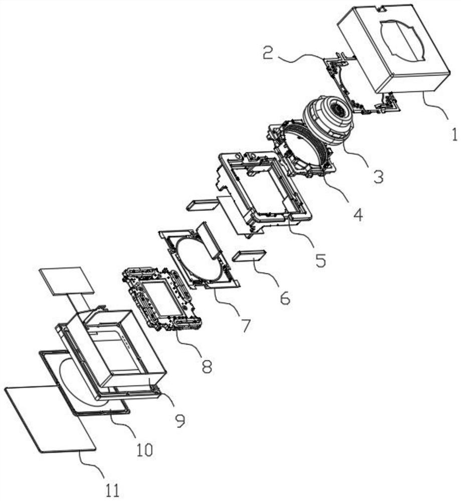
[0036] Combined with the manual figure 1 with figure 2 The sensor anti-shake motor shown includes an external support structure composed of an outer shell 1 and a bottom plate 11. A focus mechanism, a carrier 5, an anti-shake mechanism and a conductive mechanism are installed in the external support structure. The focus mechanism is respectively The front suspension wire spring 2 and the rear suspension wire spring 7 are connected with the carrier 5, the anti-shake mechanism is connected with the carrier 5 through the anti-shake suspension wire 10, and the conductive mechanism is connected with the anti-shake mechanism, the front suspension wire spring 2, The rear suspension wire spring 7 is electrically connected with the anti-shake mechanism. Working principle: The carrier 5 is fixed or detachably connected to the external support structure. The focusing mechanism can rely on the front suspension wire spring 2 and the rear suspension wire spring 7 to move back and forth ax...
Embodiment 2
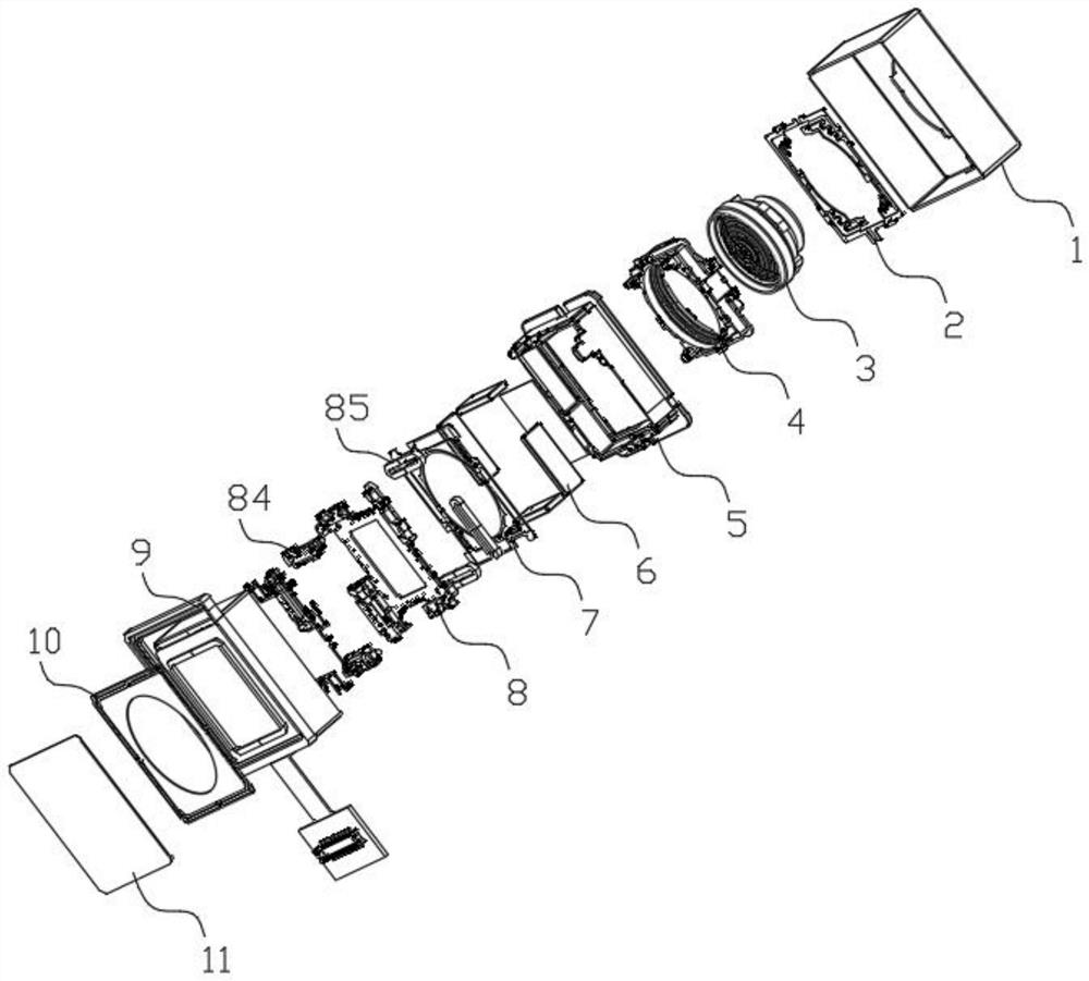
[0039] As one of the key technical innovation points of the present invention, on the basis of Embodiment 1 in conjunction with the description attached Image 6 with Figure 7 As shown, the anti-shake mechanism includes a sensor bracket 8, the outside of the sensor bracket 8 is connected to the carrier 5 through the anti-shake suspension wire 10, the sensor bracket 8 includes a bracket body 81, and the bracket body 81 A first installation cavity 82 for installing an imaging sensor is provided at the central position, and a plurality of second installation cavities 83 for installing a coil support 84 are provided on the side wall of the support body 81, and a coil 85 is installed on the coil support 84 , the position of any one of the coils 85 corresponds to the position of the magnet 6 . As one of the preferred layout methods, there are four magnets 6 and four coil supports 84 , which are arranged around the support body 81 in an axisymmetric or centrosymmetric manner. The ...
Embodiment 3
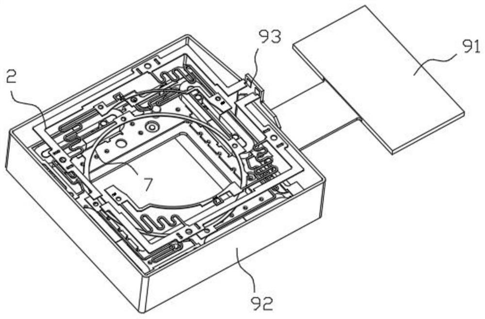
[0043] On the basis of Embodiment 2, as one of another technical improvement point of the present application, in combination with the description attached Figure 3-Figure 5 As shown, the conductive mechanism includes an FPC soft board 9, and the FPC soft board 9 includes a connecting part 91, a transmission part 92 and a backboard 95, a plug 94 is arranged on the connecting part 91, and a plug 94 is arranged on the backboard 95. There is a connecting contact electrically connected to the third contact 862, so that any coil 85 is electrically connected to the plug 94; The first contact 93 that the rear suspension wire spring 7 communicates with. The electrical signal that drives the coil 85 to generate magnetic force passes through the plug 94, the connecting portion 91, the transmission portion 92, the connecting contact, the third contact 862, the metal conductor 86, and finally reaches the coil 85. The coil is energized to generate magnetic force and the magnet 6 generates...
PUM
 Abstract
Description
Claims
Application Information
 - R&D
- Intellectual Property
- Life Sciences
- Materials
- Tech Scout
- Unparalleled Data Quality
- Higher Quality Content
- 60% Fewer Hallucinations
Browse by: Latest US Patents, China's latest patents, Technical Efficacy Thesaurus, Application Domain, Technology Topic, Popular Technical Reports.
© 2025 PatSnap. All rights reserved.Legal|Privacy policy|Modern Slavery Act Transparency Statement|Sitemap|About US| Contact US: help@patsnap.com