
Silicon-based integrated optical frequency transfer system

A technology of integrated optics and frequency transmission, applied in transmission systems, electromagnetic wave transmission systems, optical fiber transmission, etc., can solve problems such as the influence of frequency transmission accuracy, performance-limited systems, and complex stability of free-space optical devices

Active Publication Date: 2021-08-13
SHANGHAI JIAO TONG UNIV
View PDF7 Cites 2 Cited by
  • Summary
  • Abstract
  • Description
  • Claims
  • Application Information

AI Technical Summary

Problems solved by technology

However, part of the performance of fiber optic frequency transmission is currently limited by the out-of-band noise of the system. In order to overcome this problem, France proposed the use of temperature control to suppress the impact of out-of-band noise in 20xx. The system is more complex and when the master-slave The inconsistency of the terminal separation temperature will have a greater impact on the accuracy of frequency transmission [see Stefani, F., Lopez, O., Bercy, A., Lee, W.K., Chardonnet, C., Santarelli, G. , Pottie, P.E. and Amy-Klein, A., 2015. Tackling the limits of optical fiber links. JOSA B, 32(5), pp.787-797.]
In 20xx, NIST in the United States proposed to use free-space optical devices to build an optical frequency transfer system, but based on free-space optical devices, it is more complex and less stable [see Williams, P.A., Swann, W.C. and Newbury, N.R., 2008. High-stability transfer of an optical frequency over long fiber-opticlinks. JOSA B,25(8),pp.1284-1293.]
However, the large size of PLC photonic integration is not suitable for CMOS-compatible optoelectronic integration [cf. Akatsuka, T., Goh, T., Imai, H., Oguri, K., Ishizawa, A., Ushijima, I., Ohmae, N., Takamoto, M., Katori, H., Hashimoto, T. and Gotoh, H., 2020. Optical frequency distribution using laser repeaterstations with planar lightwave circuits. Optics express, 28(7), pp.9186-9197. ]

Method used


Image

  • Silicon-based integrated optical frequency transfer system
  • Silicon-based integrated optical frequency transfer system
  • Silicon-based integrated optical frequency transfer system

Examples


Embodiment Construction

[0017] Below in conjunction with embodiment and accompanying drawing, the present invention will be further described, and present embodiment is carried out on the premise of technical solution of the present invention, has provided detailed implementation mode and and specific work flow, but protection scope of the present invention is not limited to the following the described embodiment.

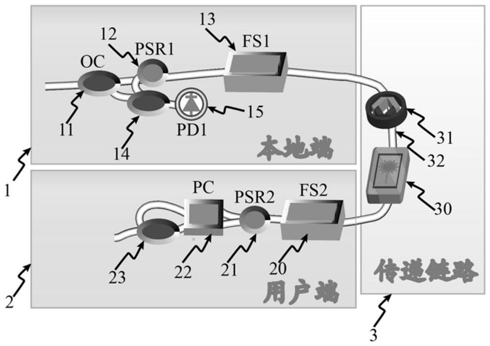
[0018] Please see first figure 1 , figure 1 It is a schematic structural diagram of the silicon-based integrated optical frequency transmission system of the present invention. It can be seen from the figure that the silicon-based integrated optical frequency transmission system of the present invention includes a local terminal 1, an optical fiber link 3 and a user terminal 2:

[0019] The local terminal 1 is composed of a first optical coupler 11, a first polarization rotating beam splitter 12, a first double-parallel Mach-Zehnder type frequency shifter 13, a second optical coupler 14 ...


PUM


Abstract

A silicon-based integrated optical frequency transfer system comprises a local end, an optical fiber link and a user end, and has the advantages of low system noise, compact structure, simple packaging and high reliability.

Description

technical field [0001] The invention relates to optical fiber time and frequency transmission, in particular to a silicon-based integrated optical frequency transmission system. Background technique [0002] Since the frequency of optical atomic clocks is several orders of magnitude higher than that of microwave atomic clocks, optical atomic clocks, including optical ion clocks and optical lattice clocks, can achieve higher frequency stability and accuracy, and the current frequency accuracy is close to 10 -19 It is more than an order of magnitude higher than the existing microwave atomic clocks, and there is still a huge room for improvement. It has become a strong competitor for the next generation of time-frequency benchmarks. The most widely used satellite-based space-based frequency transfer can only achieve 10 -15 / day frequency transmission stability. In addition to the time-frequency transmission method based on space-based satellites, the optical frequency transmi...

Claims


Application Information

Patent Timeline
IPC IPC(8): H04B10/2507H04B10/079
CPCH04B10/2507H04B10/0795H04B2210/25
Inventor 胡亮陆梁军吴龟灵周林杰刘娇陈建平
Owner SHANGHAI JIAO TONG UNIV
Learn More