
Power unit structure for improving amplification efficiency

A power unit and main amplifier technology, which is applied in the direction of improving amplifiers to improve efficiency, components of amplifiers, amplifiers, etc., can solve problems such as increased conduction angles, and achieve the effects of maintaining linear characteristics, easy integration, and improving efficiency

Pending Publication Date: 2021-08-13
SUZHOU INNOTION TECH
View PDF0 Cites 1 Cited by
  • Summary
  • Abstract
  • Description
  • Claims
  • Application Information

AI Technical Summary

Problems solved by technology

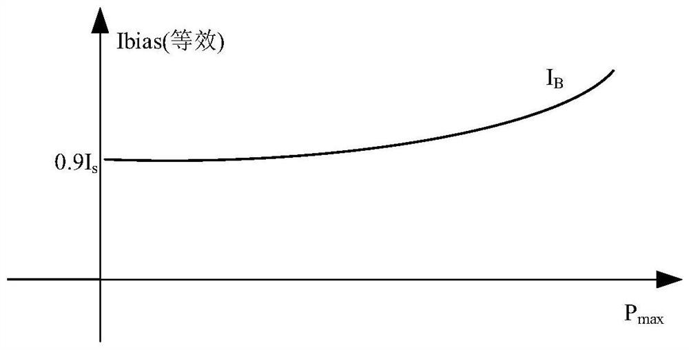
For traditional Class AB amplifiers, when outputting high power, due to the self-bias effect of the amplifier, the high-peak pulse signal leads to the equivalent bias point I B greatly improved, the conduction angle increases, such as figure 1 As shown, the improvement of power amplifier efficiency encounters a bottleneck

Method used


Image

  • Power unit structure for improving amplification efficiency
  • Power unit structure for improving amplification efficiency
  • Power unit structure for improving amplification efficiency

Examples


Embodiment 1

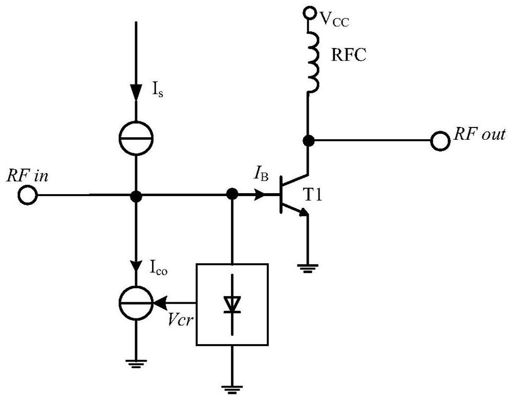
[0026] Such as figure 2 As shown, a power unit structure for improving amplification efficiency disclosed in this embodiment includes a main amplifier tube T1 and a constant current source, the base of the main amplifier tube T1 is connected to the radio frequency input terminal RFin, and the collector is connected to the power output terminal RFout, connected to the voltage V through the RF choke RFC CC , the emitter is grounded; the constant current source is connected to the base of the main amplifier tube T1, and its output current I S ; Also includes a bias compensation circuit and a detector tube, the bias compensation circuit produces a bias compensation current I CO , select a reasonable number of transistors as the detector tube, connect the RF input terminal RFin, generate a voltage control signal Vcr, and control the bias compensation current I CO the size of.

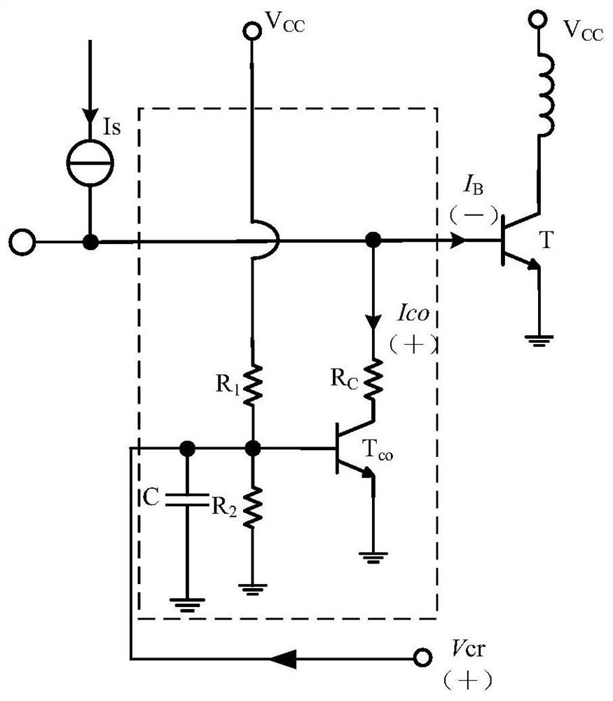
[0027] Such as image 3 As shown, the bias compensation circuit includes a capacitor C, a resistor R...

Embodiment 2

[0034] In Embodiment 1, the detection tube uses the radio frequency input terminal RFin as the power detection terminal to solve the problem. If the output terminal RFout of the power unit structure is used as the power detection terminal, it is still applicable, such as Figure 5 As shown, the detector tube in this embodiment is connected to the output terminal RFout of the power unit structure.

Embodiment 3

[0036] In Embodiments 1 and 2, the detection signal of the detection tube is used to control the bias compensation current, and the constant current source is used to realize the indirect dynamic control of the bias point of the main amplifier tube. The detection signal can also be used to directly control the bias point of the main amplifier tube.

[0037] Such as Figure 6As shown, in this embodiment, a constant current source control circuit is used to replace the bias compensation circuit. The voltage control signal Vcr output by the detector tube passes through the constant current source control circuit to control the output current I of the constant current source. S , at this time the output current I of the constant current source S as a direct bias current. With the increase of the voltage control signal Vcr, the direct bias current I can be made through a reasonable constant current source control circuit S reduced, the same effect as in Embodiments 1 and 2 can be...


PUM


Abstract

The invention discloses a power unit structure for improving amplification efficiency. The power unit structure comprises a main amplifier tube T1, a constant current source, a bias compensation circuit and a detector tube, the bias compensation circuit comprises a capacitor C, resistors R1, R2 and RC and a compensation amplifier tube Tco; the collector electrode of the compensation amplifier tube Tco is connected with the base electrode of the main amplifier tube T1 through a resistor RC; the base electrode of the compensation amplifier tube Tco is connected with voltage VCC through a resistor R1 and is grounded through a resistor R2 and a capacitor C which are connected in parallel, and the emitter electrode of the compensation amplifier tube Tco is grounded; and the detector tube is connected with a radio frequency input end RFin, generates a voltage control signal Vcr, and is connected to a base electrode of the compensation amplifier tube Tco to control the magnitude of the bias compensation current ICO. When the input power is increased, the bias point descends actively to compensate the rising of the equivalent bias point caused by self-bias, so that the conduction angle can maintain the size during low-power output, the efficiency of the traditional structure is improved, and the linear characteristic of the original structure is maintained.

Description

technical field [0001] The invention relates to the field of power amplification, in particular to a power unit structure for improving amplification efficiency. Background technique [0002] Pulse radar is widely used in meteorology, marine sensing, navigation and national defense and other fields. As an important part of the RF front-end, the power amplifier's characteristics are crucial to the radar performance. For traditional Class AB amplifiers, when outputting high power, due to the self-bias effect of the amplifier, the high-peak pulse signal leads to the equivalent bias point I B greatly improved, the conduction angle increases, such as figure 1 As shown, the improvement of power amplifier efficiency encounters a bottleneck. Contents of the invention [0003] The purpose of the present invention is to provide a new type of power unit structure, which dynamically regulates the bias point of the main power amplifier tube, so that the bias current is reduced durin...

Claims


Application Information

Patent Timeline
Patent Type & Authority Applications(China)
IPC IPC(8): H03F1/32H03F1/02H03F3/21
CPCH03F1/0266H03F1/32H03F3/21
Inventor 高怀王锋田婷
Owner SUZHOU INNOTION TECH
Learn More