
Moving speed detection method of nondestructive testing device and system device of moving speed detection method

A non-destructive testing and moving speed technology, applied in radio wave measurement systems, measuring devices, speed/acceleration/shock measurement, etc. Easy to install and apply effects

Pending Publication Date: 2021-08-13
EDDYSUN (XIAMEN) ELECTRONICS CO LTD
View PDF0 Cites 0 Cited by
  • Summary
  • Abstract
  • Description
  • Claims
  • Application Information

AI Technical Summary

Problems solved by technology

However, the environmental conditions of the production site are generally relatively harsh, and the machinery and equipment also need some coordinating equipment such as lubricating oil to run. It can be set as a relatively thin sheet, and the detection trolley does not need a large volume, while the optical encoder speedometer generally needs a relatively large volume to calculate the speed through rotation, which adds a considerable part of the burden to the detection trolley device

Method used


Image

  • Moving speed detection method of nondestructive testing device and system device of moving speed detection method
  • Moving speed detection method of nondestructive testing device and system device of moving speed detection method
  • Moving speed detection method of nondestructive testing device and system device of moving speed detection method

Examples


Embodiment approach 1

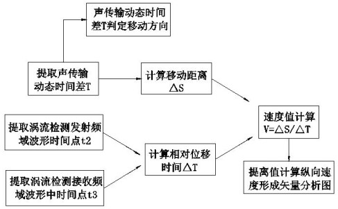
[0039] Such as figure 2As shown, a moving speed detection method of a non-destructive testing device is used to detect and calculate the relative displacement speed between the non-destructive testing device and the detection object, which is characterized in that it is performed by detecting the coil acoustic emission and reception time, and the eddy current frequency domain waveform time The calculation of the displacement velocity, the specific method steps are as follows:

[0040] a. Extract the dynamic time difference T of acoustic transmission: extract the dynamic time t1 of the acoustic transmission between the coil acoustic emission and reception when the detection object and the eddy current detection device are in relative motion, and the on-site calibration acoustic emission and acoustic transmission when the detection object and the eddy current detection device are relatively stationary The acoustic transmission static time t0 between the receiving coils is comp...

Embodiment approach 2

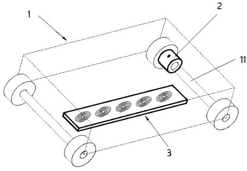
[0059] Such as Figure 8 As shown, the difference from Embodiment 1 is that a coil (34) with an acoustic vibrating plate (35) equidistant from the external eddy current detection coil (31) is set inside the detection device to extract the relatively static on-site environment standard environment where the air flow is relatively static. The sound propagation velocity value V0 is used to calculate the moving distance △S (because the air flow inside the detection device is relatively static)


PUM


Abstract

The invention relates to a moving speed detection method of a nondestructive testing device and a system device of the moving speed detection method. The system device comprises a substrate 32 and a plurality of eddy current testing coils 31 arranged on the same plane of the substrate, and is characterized in that two of the eddy current testing coils 31 are selected as an acoustic emission coil 311 and an acoustic receiving coil 312; the coil of the acoustic emission coil 311 is provided with an acoustic vibration sheet 33. The relative displacement speed is calculated, speed detection can be achieved without adding an additional speed detection sensor in eddy current detection, and integration and simplification of an eddy current detection sensor probe are facilitated.

Description

technical field [0001] The invention relates to the technical field of non-destructive testing, in particular to the detection of the moving speed of an eddy current non-destructive testing device, in particular to a method for detecting the moving speed of a non-destructive testing device and a system device thereof. Background technique [0002] With the development of modern industry, the demand for measurement, diagnosis, testing and monitoring of non-destructive testing in the production process and application process is increasing. As a simple and high-precision electromagnetic non-destructive testing, eddy current testing is very important because of its zero loss. Contact scanning detection stands out in the detection system of industrial production and product application, occupying an important application position. [0003] In order to adapt to the current ever-changing production and application automation, the intelligent function requirements of non-destructiv...

Claims


Application Information

Patent Timeline
IPC IPC(8): G01S15/58G01S15/62G01P3/49G01P13/04
CPCG01P3/49G01P13/045G01S15/58G01S15/62
Inventor 林俊明卢超沈淮吴晓瑜宋凯卢聪赟
Owner EDDYSUN (XIAMEN) ELECTRONICS CO LTD
Learn More