
Monitoring Method of Stress Change Based on Fiber Bragg Grating

A technology of optical fiber grating and stress change, which is applied in the direction of measuring, measuring force, and measuring device by measuring the change force of the optical properties of the material when it is stressed, which can solve the problems of poor storage efficiency, difficult information replication, and inconsistent information storage mode. Standardization and other issues to achieve the effect of improving the performance of the duration, improving the efficiency of information storage, and facilitating expansion and repair

Active Publication Date: 2021-09-24
SEU INTELLIGENCE SYST CO LTD
View PDF0 Cites 0 Cited by
  • Summary
  • Abstract
  • Description
  • Claims
  • Application Information

AI Technical Summary

Problems solved by technology

[0007] In order to solve the above problems, the present invention provides a stress change monitoring method and transmission method based on fiber gratings, which effectively avoids the stress information in the prior art during the information storage of the stress information. There are many information types and different types of information The storage mode is not standardized, and the amount of information is increasing, which makes the storage efficiency poor and makes it difficult to copy the information later. During the information storage of the stress information, the performance and storage conditions of the terminal platform used cannot be well monitored.

Method used


Image

  • Monitoring Method of Stress Change Based on Fiber Bragg Grating
  • Monitoring Method of Stress Change Based on Fiber Bragg Grating
  • Monitoring Method of Stress Change Based on Fiber Bragg Grating

Examples


Embodiment Construction

[0081] The present invention will be further described below in conjunction with the accompanying drawings and embodiments.

[0082] Such as Figure 1-Figure 5 As shown, the stress change monitoring method based on fiber Bragg grating includes:

[0083]A system for implementing a stress change monitoring method based on a fiber Bragg grating, the system includes a terminal platform and several microprocessors of a fiber Bragg grating-based buried pipeline stress detection platform communicatively connected to the terminal platform, the fiber Bragg grating-based buried pipeline The pipeline stress detection platform also includes a fiber grating sensor, the fiber grating sensor is connected to the spectrum demodulator, and the microprocessor is connected to the spectrum demodulator; the fiber grating-based buried pipeline stress detection platform is based on the fiber grating The real-time stress online monitoring device for buried pipeline welds. In this way, the fiber grat...


PUM


Abstract

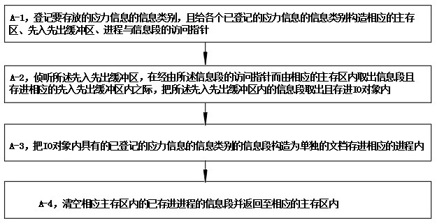
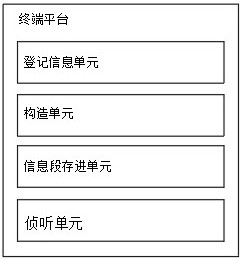
A method for monitoring stress changes based on fiber gratings, comprising: a registration information unit running on a terminal platform for registering information categories of stress information to be stored; a construction unit running on a terminal platform for giving each registered The information category of the stress information constructs the corresponding main storage area, first-in-first-out buffer, process and information segment access pointer; the information segment running on the terminal platform is stored in the unit, and is used to transfer the information segment through the access pointer of the information segment The information segments in the main storage area are stored in the corresponding first-in-first-out buffer; effectively avoiding the stress information in the prior art during the information storage of the stress information, there are many information categories of the stress information, the information storage modes of different categories are not standardized, and the information The increasing amount makes the storage efficiency poor and makes it difficult to copy the information later, and the performance and storage conditions of the terminal platform used during the information storage of the stress information cannot be well monitored.

Description

technical field [0001] The invention relates to the technical field of optical fiber gratings, in particular to a stress change monitoring method based on optical fiber gratings. Background technique [0002] A fiber grating is a diffraction grating formed by periodically modulating the refractive index of the fiber core in a certain way, and is a passive filter device. Because the fiber grating has the advantages of small size, small fusion loss, full compatibility with optical fibers, and can be embedded in smart materials, and its resonant wavelength is sensitive to changes in the external environment such as temperature, strain, refractive index, and concentration, so in the production of fiber lasers , optical fiber communication and sensing fields have been widely used. On the other hand, as the stress changes of buried pipelines become more and more complex, according to the performance characteristics of fiber gratings, there is a stress detection platform for burie...

Claims


Application Information

Patent Timeline
Patent Type & Authority Patents(China)
IPC IPC(8): G01L1/24G08C23/06
CPCG01L1/246G08C23/06
Inventor 郝品山吴小虎范克州
Owner SEU INTELLIGENCE SYST CO LTD
Learn More