Electrolytic purifier
A technology of purifiers and electrolytic sheets, applied in chemical instruments and methods, water treatment parameter control, special treatment targets, etc., can solve the problems of high purchase cost, inconvenient portability, complex structure, etc., and achieve reduced overall volume and compact internal structure , Easy to carry and use when going out
- Summary
- Abstract
- Description
- Claims
- Application Information
AI Technical Summary
Problems solved by technology
Method used
Image
Examples
Embodiment 1
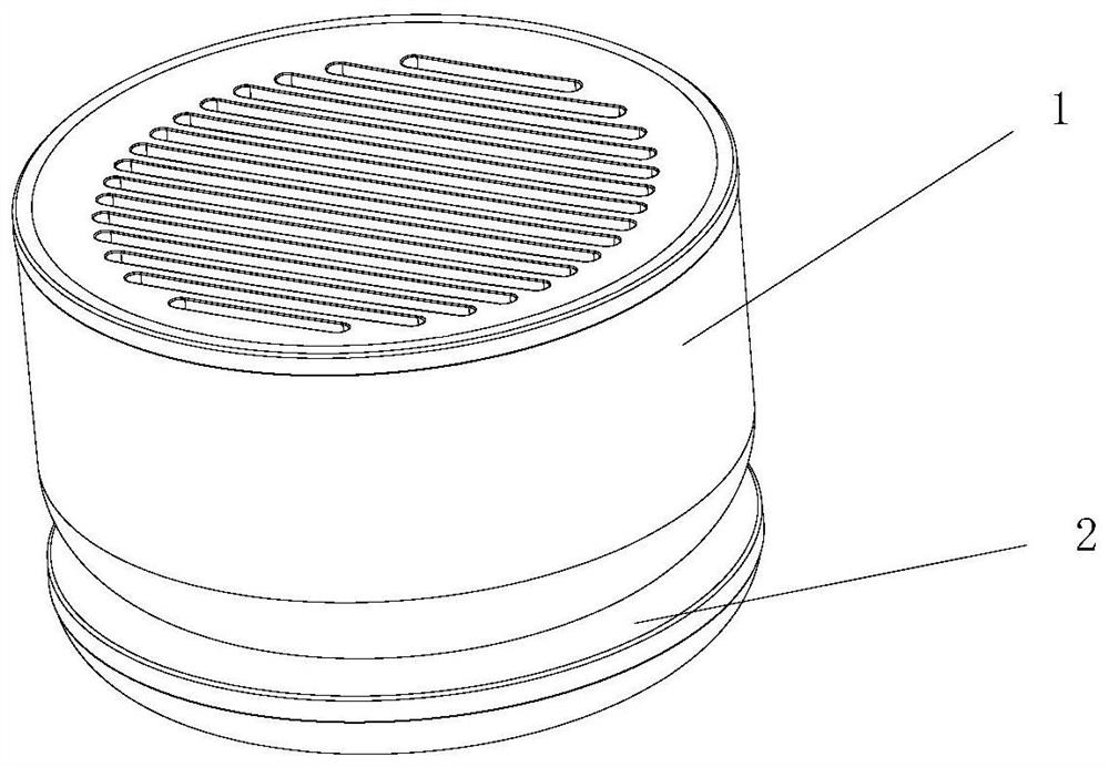
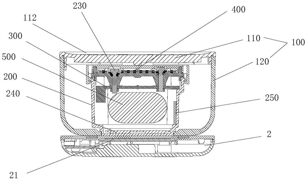
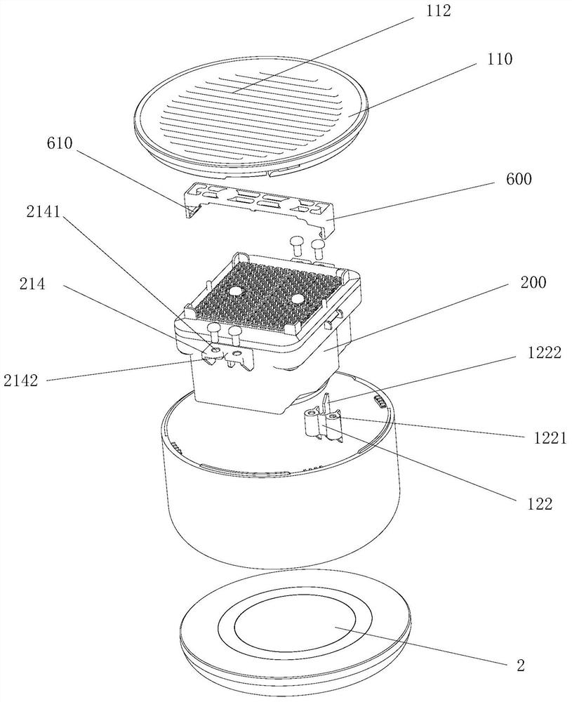
[0057] Such as Figure 1-12 As shown, the present invention provides an electrolytic purifier, including a body 1 and a charging base 2, the charging base 2 is located below the body 1, and when the body 1 is placed on the charging base 2, the charging base 2 can charge the body 1. The body 1 includes a casing 100, an electric control box 200 installed in the casing 100, a control board 300, and an electrolytic sheet assembly 400, wherein the electric control box 200 includes a box body 210 and a box cover 220, and the box body 210 is provided with a power supply battery The placement cavity 211 of 500, the placement cavity 211 matches the shape of the power supply battery 500, and the power supply battery 500 is installed in the placement cavity 211 in a set direction limit, so that the internal structure of the electric control box 200 is compact, which is conducive to reducing the overall volume of the electric control box 200; The control board 300 is installed in the box ...
Embodiment 2
[0084] The difference between this embodiment and the first embodiment lies in the structure of the electric control box.
[0085] Such as Figure 13-Figure 14 As shown, the box cover 220 is provided with through holes for the positive electrode conductor 230 and the negative electrode conductor 230 to pass through respectively, and a shunt rib 228 extending from the center of the box cover 220 to the surroundings is provided between the through holes, and the electrolytic sheet assembly 400 passes through the shunt An overcurrent gap is formed between the rib 228 and the box cover 220 , and the electrolytic sheet assembly 400 is supported on the shunt rib 228 and does not adhere to the upper surface of the box cover 220 . The top surface of the electric control box 200 includes a top plane and a water guiding slope 229 arranged around the top plane, the flow distribution rib 228 is located on the top plane, and the water guiding slope 229 is inclined downward from the top pla...
Embodiment 3
[0088] The difference between the present embodiment and the first embodiment is that the electric control box is clamped and fixed with the bottom case.
[0089] Such as Figure 16-Figure 19As shown, the first installation part is the third boss 216 protruding from the side wall of the electric control box 200, the third boss 216 is provided with a limit groove 2161, and the second installation part is arranged on the inner wall of the bottom case 120 The fourth boss 124, the fourth boss 124 is provided with a limiting rib 1241, the fourth boss 124 overlaps with the third boss 216, and at the same time the limiting rib 1241 and the limiting groove 2161 limit card catch. The fixed connection between the electric control box 200 and the bottom case 120 is realized by the clamping and fixing of the third boss 216 and the fourth boss 124 , and the plugging of the glue filling air cavity 215 and the installation port 123 .
[0090] Such as Figure 16 and Figure 17 As shown, t...
PUM
 Abstract
Description
Claims
Application Information
 - R&D
- Intellectual Property
- Life Sciences
- Materials
- Tech Scout
- Unparalleled Data Quality
- Higher Quality Content
- 60% Fewer Hallucinations
Browse by: Latest US Patents, China's latest patents, Technical Efficacy Thesaurus, Application Domain, Technology Topic, Popular Technical Reports.
© 2025 PatSnap. All rights reserved.Legal|Privacy policy|Modern Slavery Act Transparency Statement|Sitemap|About US| Contact US: help@patsnap.com


