
Uniform tension conveying device for computer communication cables

A communication cable and conveying device technology, which is applied in the directions of transportation and packaging, delivery of filamentous materials, thin material processing, etc. It can solve the problems of communication cable damage, improper adjustment, and large cable tension.

Active Publication Date: 2021-08-13
合肥九州龙腾科技成果转化有限公司
View PDF9 Cites 7 Cited by
  • Summary
  • Abstract
  • Description
  • Claims
  • Application Information

AI Technical Summary

Problems solved by technology

[0003] At present, the cable is basically pulled by the machine, but because the force of the cable during the transportation process is relatively complicated, such as turning a corner or threading the cable in the protective tube, etc., the tension on the cable itself is not uniform
Because excessive pulling force may damage the communication cable, it is necessary to achieve uniform pay-off to avoid excessive tension on the cable
[0004] But now most of the pay-off speed is adjusted through manual monitoring, and there are problems such as legacy, lag, or improper adjustment, which makes the tension on the cable uneven during the pay-off process, increasing the risk of damage
[0005] In summary, there are obviously inconveniences and defects in the actual use of the existing technology, so it is necessary to improve

Method used

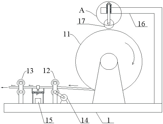
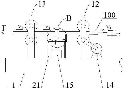
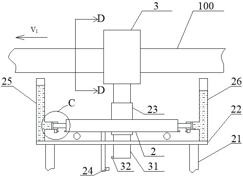

Image

  • Uniform tension conveying device for computer communication cables
  • Uniform tension conveying device for computer communication cables
  • Uniform tension conveying device for computer communication cables

Examples


Embodiment Construction

[0031] In order to make the objectives, technical solutions and advantages of the present invention clearer, the present invention will be described in further detail below in conjunction with the accompanying drawings and embodiments. It should be understood that the specific embodiments described here are only used to explain the present invention and are not intended to limit the invention.

[0032] In describing the present invention, it should be understood that the terms "center", "longitudinal", "transverse", "length", "width", "thickness", "upper", "lower", "front", " Back", "Left", "Right", "Vertical", "Horizontal", "Top", "Bottom", "Inner", "Outer", "Clockwise", "Counterclockwise", "Axial", The orientation or positional relationship indicated by "radial", "circumferential", etc. is based on the orientation or positional relationship shown in the drawings, and is only for the convenience of describing the present invention and simplifying the description, rather than ...


PUM


Abstract

The invention relates to the technical field of cable conveying, and provides a uniform tension conveying device for computer communication cables. The uniform tension conveying device comprises a cable roller erected on a roller frame; a tension adjusting mechanism is further arranged on the roller frame; the tension adjusting mechanism comprises a driving cable clamping wheel set and a driven cable clamping wheel set which are arranged on the roller frame, and a cable penetrating cylinder connected to the cables in a penetrating mode is arranged between the driving cable clamping wheel set and the driven cable clamping wheel set; the lower portion of the cable penetrating cylinder is connected with a sliding rod, and the sliding rod is slidably connected with a guide cylinder arranged on a moving vehicle in a sleeving mode; an upper ejector rod is arranged on the upper half portion of the cable penetrating cylinder in a penetrating mode, and lower ejector rods are symmetrically arranged on the lower half portion of the cable penetrating cylinder; and the lower ejector rods are provided with cable jacking wheels for pressing and connecting the cables. Therefore, the cable penetrating cylinder is arranged on the driving cable clamping wheel set and the driven cable clamping wheel set, and meanwhile, the cable penetrating cylinder is connected with the moving vehicle; and the cable penetrating cylinder sensitively senses change of the pulling force, so that self-adjustment of the tension force of the cables is realized, and safe and stable conveying of the cables is guaranteed.

Description

technical field [0001] The invention belongs to the technical field of cable transmission, and in particular relates to a computer communication cable uniform tension transmission device. Background technique [0002] At the installation and construction site of the communication cable, the cable reel is usually set up on site so that it can be rotated, and the cable is paid out by pulling. [0003] At present, the cable is basically pulled by a machine, but because the force of the cable during the transportation process is relatively complicated, such as turning or threading in the protective tube, the tension on the cable itself is not uniform. Because excessive pulling force may damage the communication cable, it is necessary to achieve uniform pay-off to avoid excessive tension on the cable. [0004] However, most of the current pay-off speed is adjusted through manual monitoring. There are problems such as legacy, lag, or improper adjustment, which makes the tension o...

Claims


Application Information

Patent Timeline
IPC IPC(8): B65H49/30B65H59/06B65H51/10B65H57/12B65H59/38B65H59/40
CPCB65H49/30B65H51/10B65H57/12B65H59/06B65H59/388B65H59/40B65H2701/34
Inventor 谷雨朱焕勇宋铖
Owner 合肥九州龙腾科技成果转化有限公司
Learn More