
Welding forming machine as well as production line and production method of cement floor support plate

A production method and technology of floor decks, applied in the field of cement floor decks, can solve problems such as reduced production efficiency, large and clumsy cost of process equipment, and impact on production costs, so as to reduce production and equipment costs, and achieve stable and reliable welding and connection. reliable performance

Pending Publication Date: 2021-08-13
李世捷
View PDF0 Cites 0 Cited by
  • Summary
  • Abstract
  • Description
  • Claims
  • Application Information

AI Technical Summary

Problems solved by technology

In the application of floor slabs, although the production technology of reinforced truss slabs is mature, the scope of application is limited due to the inability to combine the metal base plate with the later decoration. Generally, it can only be used in steel structure industrial buildings or large open commercial buildings. Buildings, and the cement floor deck successfully overcomes the disadvantages of the steel truss floor deck. With the development of green buildings and prefabricated buildings, more and more attention has been paid
[0003] However, the existing cement floor slab production process is cumbersome and has low production efficiency. The floor slab production disclosed in the prior art still has the following problems: 1. The combined connection of the cement floor slab is only connected by bolts or screws, and it must be connected many times. Holes are drilled and the quantity is large, which requires extremely high performance of production equipment, resulting in high cost of production equipment and low efficiency, which directly affects production costs; 2. The production process of the bottom formwork on the upper truss reinforcement under the bolt or screw connection method must be used in the production process, which requires post-production Turning over the components, this process equipment is bulky and clumsy, and the cost is high, the production cost is high, and the production efficiency is low; 3. Although the traditional floor deck production adopts the welding connection method, it is convenient to produce, but the equipment must have an electrode on the top and bottom, which cannot be applied 4. Although the existing steel plate combined cement floor slab adopts the welding connection method to overcome the disadvantages of traditional cement floor bearings using bolts or screws, but because there is no supporting automatic welding equipment, the The production efficiency is reduced, restricting its production development

Method used


Image

  • Welding forming machine as well as production line and production method of cement floor support plate
  • Welding forming machine as well as production line and production method of cement floor support plate
  • Welding forming machine as well as production line and production method of cement floor support plate

Examples


Embodiment 1

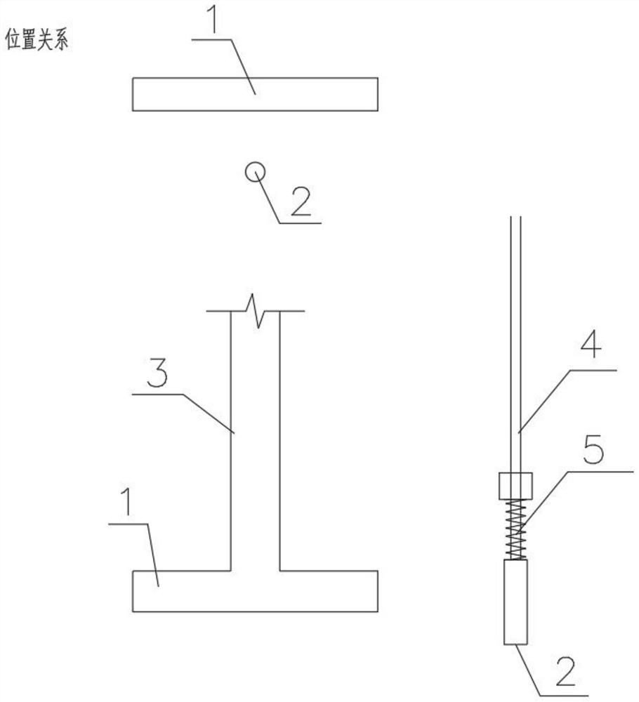
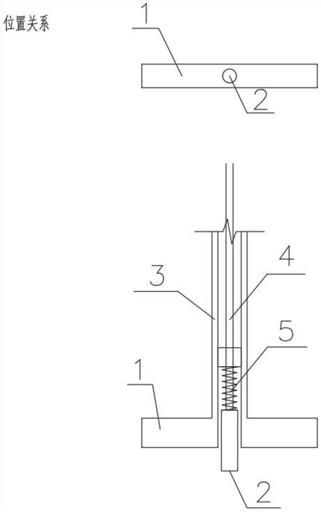
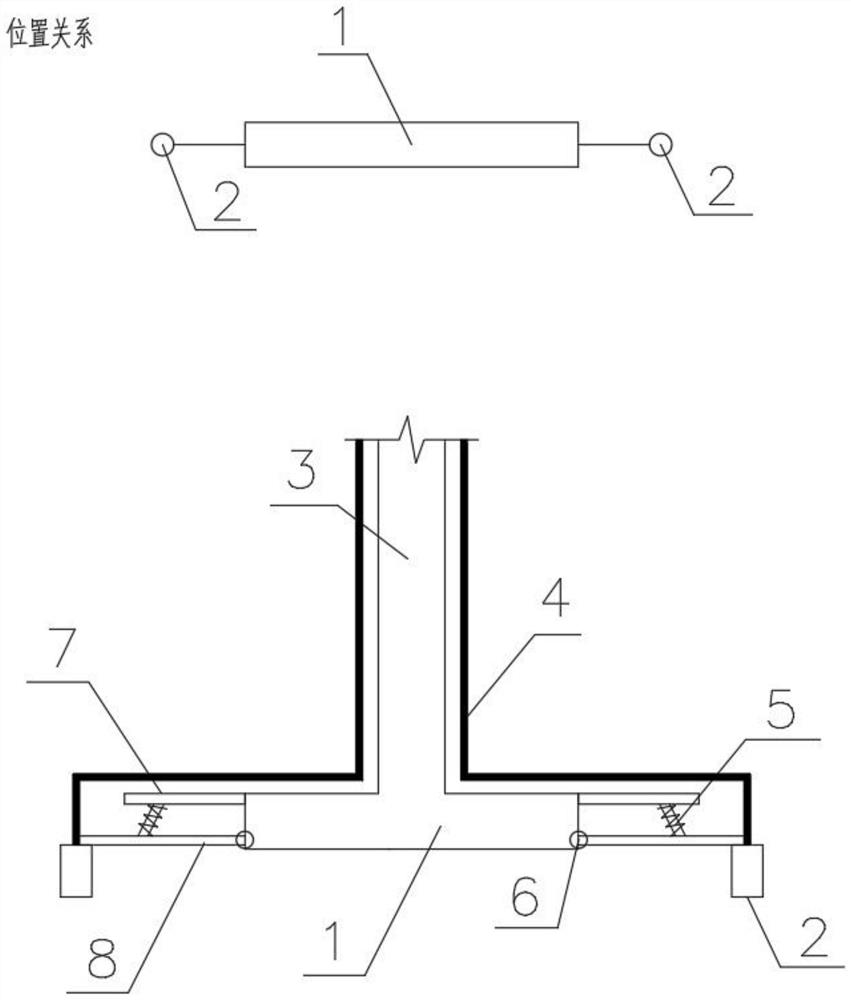
[0047] Such as Figure 1-4 As shown, this embodiment proposes a welding forming machine, including a positive electrode 1 and a negative electrode 2 both arranged on the upper part of the workpiece. sides.

[0048] Such as figure 1 As shown, it also includes a positive electrode copper column 3, the bottom of which is connected to the positive electrode 1; one side of the positive electrode copper column 3 is provided with a negative electrode copper column 4, and the negative electrode copper column 4 is connected to the negative electrode 2, and the negative electrode copper column 4 is also sleeved There are springs 5. Wherein the bottom end of spring 5 is fixedly connected with negative electrode 2 and / or negative electrode copper column 4, and the upper end of spring 5 is fixedly connected with fixed block, and this fixed block is fixedly connected with the main body of welding molding machine, thereby makes under the effect of spring 5, The negative electrode 2 drives...

Embodiment 2

[0060] Such as Figure 5-10 As shown, this embodiment proposes a cement floor deck production line, including intelligent assembly equipment for steel mesh and steel truss;

[0061] Automatic welding forming machine for steel mesh and steel truss used to weld steel mesh and steel truss to form steel skeleton;

[0062] Intelligent assembly equipment for cement floor slabs used for steel skeleton and floor slab bottom formwork assembly;

[0063] Automatic welding and forming equipment for cement floor deck. The automatic welding and forming equipment for cement floor deck includes an intelligent conveyor and a welding forming machine described in Embodiment 1. The welding forming machine is used for welding the steel skeleton and the bottom mold of the floor deck;

[0064] Components are automatically transported on the transit track and finished components are automatically off-line and put into storage.

[0065] Through technological innovation and multi-group equipment coll...


PUM


Abstract

The invention provides a welding forming machine as well as an automatic production line and a production method of a cement floor support plate. The welding forming machine comprises a positive electrode and a negative electrode which are arranged on the upper portion of a workpiece, and the negative electrode is arranged on one side of the positive electrode and / or arranged in the positive electrode and / or arranged on the two sides of the positive electrode. According to the welding forming machine as well as the automatic production line and the production method of the cement floor support plate, the design that the negative electrode is arranged on the upper portion is adopted, the positive electrode and the negative electrode which are needed during welding are arranged on the upper portion of the workpiece, the welding strength is guaranteed, the production technology requirement is met, the production technology process that a bottom formwork is arranged on the lower portion and a steel bar framework is arranged on the upper portion is successfully achieved, later plate overturning is not needed, the production efficiency is improved, the production and equipment cost is reduced, the production line is shortened, and the production space is saved.

Description

technical field [0001] The invention relates to the technical field of cement floor decking, in particular to a welding forming machine, a cement floor decking production line and a production method. Background technique [0002] In the field of construction, floor deck structures are more and more widely used. In the application of floor slabs, although the production technology of steel truss slabs is mature, the scope of application is limited due to the inability to combine the metal bottom slab with the later decoration. Generally, it can only be used in steel structure industrial buildings or large open commercial buildings. Buildings, and the cement floor deck successfully overcomes the disadvantages of the steel truss floor deck. With the development of green buildings and prefabricated buildings, more and more attention has been paid. [0003] However, the existing cement floor slab production process is cumbersome and has low production efficiency. The floor slab...

Claims


Application Information

Patent Timeline
Patent Type & Authority Applications(China)
IPC IPC(8): B23K11/02B23K11/36
CPCB23K11/02B23K11/36
Inventor 李世捷贾学国商丽华刘彬王国杰
Owner 李世捷
Learn More