
Pseudo soldering detection method, pseudo soldering detection device and preparation method of lithium battery

A detection method and detection device technology, applied in the direction of measuring devices, mechanical devices, optical devices, etc., can solve the problems of large fluctuations in manufacturing processes and raw materials, poor welding of pole pieces and tabs, and prone to false welding, etc. Achieve the effect of avoiding waste of materials and manpower, high applicability, and avoiding contact damage

Active Publication Date: 2021-08-10
ZHUHAI COSMX BATTERY CO LTD
View PDF12 Cites 1 Cited by
  • Summary
  • Abstract
  • Description
  • Claims
  • Application Information

AI Technical Summary

Problems solved by technology

There is a tab welding process in the production process of lithium-ion batteries. Affected by the large fluctuations in the manufacturing process and raw materials, sometimes there will be false welding phenomena such as weak or unwelded pole pieces and tabs.
The negative electrode of lithium-ion batteries is usually welded with nickel tab and copper foil, and the positive electrode is usually welded with aluminum metal and aluminum metal. Compared with the welding of positive tab, the welding of negative tab requires higher output energy and tighter tolerance. It is also more prone to false welding, so how to detect the false welding of the negative ear is a difficult problem faced by the industry

Method used


Image

  • Pseudo soldering detection method, pseudo soldering detection device and preparation method of lithium battery
  • Pseudo soldering detection method, pseudo soldering detection device and preparation method of lithium battery
  • Pseudo soldering detection method, pseudo soldering detection device and preparation method of lithium battery

Examples


Embodiment Construction

[0023] The present invention will be described in detail below in conjunction with the accompanying drawings. When describing the embodiments of the present invention in detail, for the convenience of explanation, the accompanying drawings showing the structure of the device will not be partially enlarged according to the general scale, and the schematic diagram is only an example, and it should not be limited here. The protection scope of the present invention. It should be noted that all the drawings are in very simplified form and use imprecise scales, which are only used to facilitate and clearly assist the purpose of illustrating the embodiments of the present invention.

[0024] like figure 1 As shown, the lithium battery pole piece generally includes a pole piece current collector 100, the pole piece current collector 100 is coated with a paste, and one end of the pole piece current collector 100 retains an empty foil that is not coated with paste, and the tab 101 (No. ...


PUM


Abstract

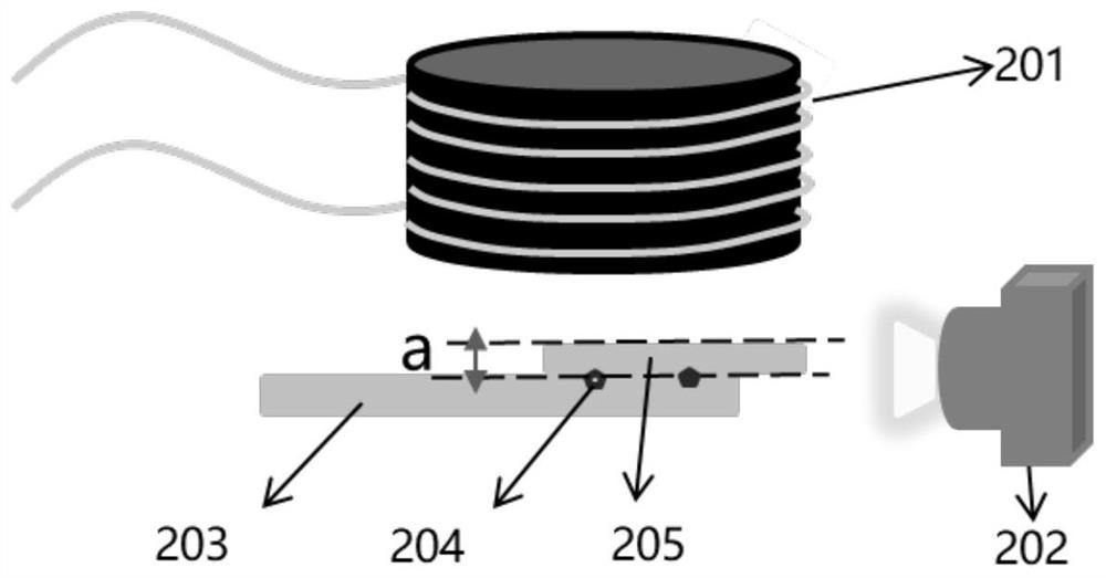
The invention relates to a pseudo soldering detection method, a pseudo soldering detection device and a preparation method of a lithium battery, wherein whether pseudo soldering exists in a first welding piece welded on a second welding piece can be detected, the first welding piece has magnetism, and the second welding piece does not have magnetism. The detection method comprises: arranging a magnetic component, and during detection, placing a first welding piece and a second welding piece on one side of the magnetic component, wherein the first welding piece is opposite to the magnetic component; arranging a distance obtaining component for obtaining distance information between the first welding piece and the second welding piece; and determining the distance between the first welding piece and the second welding piece according to the obtained distance information, comparing the maximum value with a set threshold value, and if the maximum value is greater than the set threshold value, determining that the first welding piece is pseudo soldering. According to the invention, non-contact detection is adopted, so that the damage of a detection piece caused by contact can be avoided, the product yield can be improved, detection can be carried out immediately after welding is completed, and the waste of materials and manpower in subsequent procedures caused by poor welding is avoided.

Description

technical field [0001] The invention belongs to the field of welding technology, and in particular relates to a welding quality detection method and detection device. Background technique [0002] Lithium-ion batteries have the advantages of portability and high energy density, and are currently widely used in various fields. At the same time, users have higher and higher requirements for the quality of lithium-ion batteries, so effective quality control methods are crucial. There is a tab welding process in the production process of lithium-ion batteries. Due to the large fluctuations in the manufacturing process and raw materials, sometimes there will be false welding phenomena such as weak or unwelded pole pieces and tabs. The negative electrode of lithium-ion batteries is usually welded with nickel tab and copper foil, and the positive electrode is usually welded with aluminum metal and aluminum metal. Compared with the welding of positive tab, the welding of negative ta...

Claims


Application Information

Patent Timeline
Patent Type & Authority Applications(China)
IPC IPC(8): H01M50/536G01N19/00G01B11/02
CPCG01N19/00G01B11/02Y02E60/10
Inventor 白燕邹浒刘李阳张佳雨谭熠伟
Owner ZHUHAI COSMX BATTERY CO LTD
Learn More