Sputtering film pressure sensor

A technology of pressure sensor and sputtering thin film, which is applied in the direction of measuring fluid pressure, instrument, and fluid pressure measurement by changing ohmic resistance, which can solve the problems of output drift and stress generation

Pending Publication Date: 2021-08-06
WUHAN FINEMEMS
View PDF0 Cites 0 Cited by
  • Summary
  • Abstract
  • Description
  • Claims
  • Application Information

AI Technical Summary

Problems solved by technology

[0004] The purpose of the embodiments of the present invention is to provide a sputtering thin film pressure sensor, aiming to solve the problem of output drift caused by the stress generated when the low and medium range sputtering thin film sensitive elements are installed in the prior art

Method used


Image

  • Sputtering film pressure sensor
  • Sputtering film pressure sensor
  • Sputtering film pressure sensor

Examples


Embodiment Construction

[0032] Next, the technical solutions in the embodiments of the present invention will be described in contemplation in the embodiments of the present invention, and clearly, as described herein is merely, not all of the embodiments of the present invention. Based on the embodiments of the present invention, those of ordinary skill in the art will belong to the scope of the present invention without all other embodiments obtained without creative labor.

[0033] It should be noted that if there is a directional indication (such as above, lower, left, right, post, post, ...), the directional indication is only used to interpret a particular attitude (such as the figures) Sign) The relative positional relationship between the components, movement conditions, etc., if the specific posture changes, the directional indication is also changed accordingly.

[0034] Further, in the embodiment of the present invention relates to a description of "first", "second", the description of the "fi...


PUM


Abstract

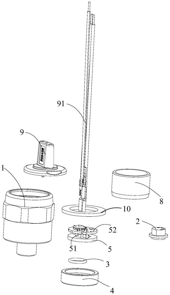
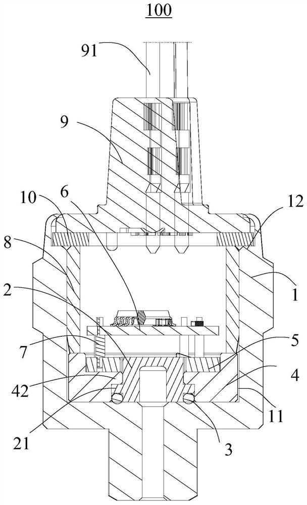
The invention provides a sputtering film pressure sensor which comprises a shell and a sputtering film sensitive element, the shell is provided with a containing cavity, and the sputtering film sensitive element and the bottom wall of the containing cavity are arranged in a sealed mode through an elastic sealing piece. According to the invention, the elastic sealing element is arranged between the sputtering film sensitive element and the bottom wall of the accommodating cavity, so that the sealing installation between the sputtering film sensitive element and the bottom wall of the accommodating cavity is realized, and therefore, the thermal stress generated by welding and the bonding stress generated by bonding in the prior art can be effectively avoided, compared with a welding process, the elastic sealing element has the advantages of low cost and simple operation, and solves the problem of temperature excursion caused by large stress generated in the installation process of the low and medium range sputtering film sensitive element.

Description

Technical field [0001] Embodiments of the present invention relate to the technical field of pressure sensors, and more particularly to a sputtering film pressure sensor. Background technique [0002] The sputtering film pressure sensor adopts a strain resistance structure, in a stainless steel substrate, a ion beam sputtering plating film, an ion beam etching, and a micro-processed process are formed into a thin film pressure sensitive structure. [0003] The low-medium medium (range of ranges from 10 mPa) in the prior art is usually used for welding installation, while the temperature during welding is more than 1700 ° C, and the temperature during welding is transmitted to the sputter film. Sensitive The surface of the component, causing the sputter film sensitive element to oxidation, which in turn leads to insufficient wire welding intensity with the pad connection, and the weld generates thermal stress, residual stress leaves, resulting in output drift of sputtering film se...

Claims


Application Information

Patent Timeline
IPC IPC(8): G01L1/22G01L9/04G01L19/00
CPCG01L1/22G01L9/04G01L19/00
Inventor 王小平曹万李凡亮吴登峰李兵施涛
Owner WUHAN FINEMEMS
Why Eureka
Try Eureka