Slender shaft part machining device and machining process thereof

A slender shaft and machining technology, which is used in positioning devices, metal processing equipment, metal processing machinery parts, etc. It is necessary to support the limit and other issues to achieve the effect of ensuring tightness, ensuring stability, and reducing the coefficient of rotational friction

Pending Publication Date: 2021-08-06
扬州鑫禾源机械有限公司
View PDF10 Cites 0 Cited by
  • Summary
  • Abstract
  • Description
  • Claims
  • Application Information

AI Technical Summary

Problems solved by technology

[0005] The technical problem to be solved by the present invention is: in order to solve the problems existing in the above-mentioned background technology, provide an improved machining device for slender shaft parts and its processing technology, so as to solve the problem of existing machining devices for similar shaft parts. When processing ultra-slender shafts with a diameter-to-length ratio of more than 1:100, the effect of supporting and limiting the slender shaft parts is poor. Bending deformation occurs, which seriously affects the quality of slender shaft turning

Method used


Image

  • Slender shaft part machining device and machining process thereof
  • Slender shaft part machining device and machining process thereof
  • Slender shaft part machining device and machining process thereof

Examples


Embodiment

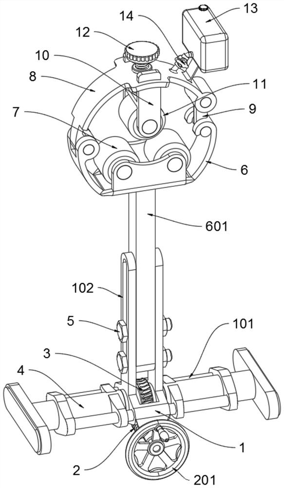
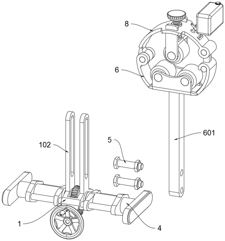
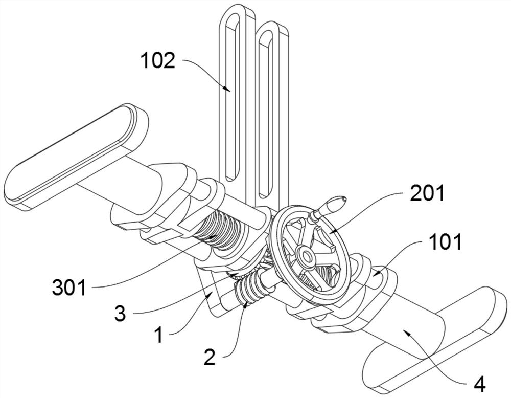
[0040] as attached figure 1 to attach Figure 7 Shown:

[0041]The present invention provides a machining device for slender shaft parts and its processing technology, which includes a support base 1, a movable support rod 4, a pressing limit frame 10 and an oil tank 13;

[0042] The top of the support chassis 1 is connected to the support seat 6, and the worm 2 and the worm wheel 3 are installed inside the support chassis 1;

[0043] Two top connecting rods 102 are arranged on the top of the support chassis 1, and a bottom connecting rod 601 is arranged at the bottom of the supporting base 6. The fastening bolt 5 is fixedly connected with the two top connecting rods 102, and the support base 6 connected to the top of the support base frame 1 can be adjusted up and down according to the height of the slender shaft parts, so that the support bottom wheel 7 fits on the thin shaft. The bottom side of long shaft parts ensures the auxiliary support effect of slender shaft parts;...


PUM


Abstract

The invention provides a slender shaft part machining device and a machining process thereof, and relates to the technical field of machining. The slender shaft part machining device comprises movable supporting rods and a pressing limiting frame; the top of a supporting bottom frame is connected with a supporting base, and a worm and a worm gear are both installed in the supporting bottom frame; the number of the movable supporting rods is two, and the movable supporting rods are connected with the supporting bottom frame; the left end of the supporting base is connected with a top plate through a movable stress rod, and the top plate is in an arc shape; the pressing limiting frame is fixedly connected with the top plate through a manual bolt; and the bottom of an oil tank communicates with an oil injection valve. According to the slender shaft part machining device, when a slender shaft part is turned, two supporting bottom wheels are attached to the bottom side of the middle of the slender shaft part for auxiliary supporting, a supporting top wheel is attached to the top side of the middle of the slender shaft part for clamping and limiting, and the slender shaft part is prevented from deforming.

Description

technical field [0001] The invention relates to the technical field of machining, in particular to a machining device and a machining process for slender shaft parts. Background technique [0002] Shaft parts with an aspect ratio greater than 25 are often encountered in machining, such as polished rods and joysticks of machine tools. Such shafts are collectively referred to as slender shafts. Compared with other types of shafts, the rigidity of the slender shaft is poor. During the turning process, due to the constant influence of cutting force, cutting heat and machining vibration, the slender shaft is very prone to stress deformation, Due to thermal deformation or tool wear, the relative position accuracy of the slender shaft and the turning tool is affected, and machining errors occur. This error is called dynamic error. Dynamic errors can also be divided into size errors and shape errors. The appearance of dynamic errors will greatly reduce the machining accuracy of the...

Claims


Application Information

Patent Timeline
Patent Type & Authority Applications(China)
IPC IPC(8): B23Q3/06B23Q11/10
CPCB23Q3/064B23Q11/10
Inventor 龚建峰柳玉春谢祥
Owner 扬州鑫禾源机械有限公司
Why Eureka
Try Eureka