Vacuum tube type steam sterilizer and sterilization method thereof

A steam sterilization, vacuum tube technology, applied in sanitary equipment, water supply devices, heating and other directions for toilets, can solve the problems of contamination of the working medium of the sealing rubber pad, slow heat transfer, short continuous working time, etc., to avoid the rubber pad Failure problems, effects of long working hours

Pending Publication Date: 2021-08-06
秦皇岛燕大源达机电科技股份有限公司
View PDF9 Cites 0 Cited by
  • Summary
  • Abstract
  • Description
  • Claims
  • Application Information

AI Technical Summary

Problems solved by technology

[0002] Liquid material sterilizer mainly has two forms: plate type sterilizer and tube type sterilizer. The plate type sterilizer has fast heat transfer, compact structure and small space occupation. However, it is not suitable for high temperature sterilization and concentrated material sterilization. At the same time, it also has sealing The rubber pad is prone to failure and the risk of material contamination by the working medium, and its continuous working time is relatively short; if the existing tubular sterilizer uses hot water as the working medium, the heat transfer is too slow. If conventional steam is used as the working medium, the material There is a problem of local overheating, and it is prone to staining, which affects its continuous working time, and the product is prone to burnt smell

Method used


Image

  • Vacuum tube type steam sterilizer and sterilization method thereof
  • Vacuum tube type steam sterilizer and sterilization method thereof

Examples


Embodiment 1

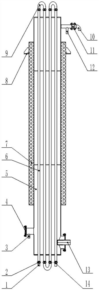
[0028] This embodiment discloses a vacuum tube type steam sterilizer as shown in 1, which includes a feed port 1, a discharge port 14, a pressure joint 2, a drain port 3, a sight glass 4, a sterilizer liner 5, a material Pipe 6, sterilizer insulation layer 7, support 8, 180° elbow 9, exhaust port 10, one-way valve 11, vacuum port 12 and steam inlet assembly 13.

[0029] The sterilizer of this embodiment is cylindrical as a whole, placed vertically, and fixed on the frame, platform or floor through the support 8. The shape of the support 8 is not fixed, and the quantity changes according to the demand. The support 8 is usually welded on the outer side of the insulation layer 7 of the sterilizer for fixing the sterilizer.

[0030] The inner side of the heat preservation layer 7 of the sterilizer in this embodiment is rock wool, and the thickness of the rock wool is determined according to actual needs. The outermost side is covered with a 304 stainless steel plate. 5 A certain...

Embodiment 2

[0037] This embodiment discloses the use of a vacuum tube type steam sterilizer. The material enters the S-shaped material tube 6 from the feed port 1 at a certain speed through the front-end conveying pump, and is discharged from the discharge port 14 . The sterilizer enters the initial debugging stage, and the vacuum pump connected to the vacuum port 12 is started, so that a certain degree of vacuum is maintained in the inner tank 5 of the sterilizer. Steam is sprayed into the sterilizer liner 5 through the steam inlet assembly 13 . Since the overall temperature of the sterilizer is still relatively low, the steam quickly condenses into water. After the steam is continuously injected for a period of time, the temperature in the inner tank 5 of the sterilizer is slightly improved.

[0038] The steam is sprayed into the sterilizer liner 5 through the steam inlet assembly 13, and exchanges heat with water. Since the inner tank 5 of the sterilizer maintains a certain degree of...

Embodiment 3

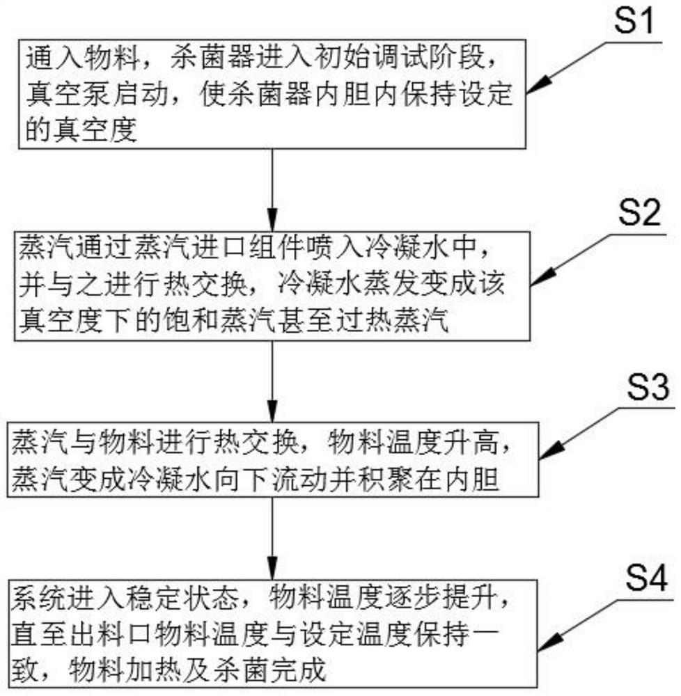
[0043] This embodiment discloses as figure 2 A sterilizing method of a vacuum tube type steam sterilizer shown comprises the following steps:

[0044] S1 feeds the material, the sterilizer enters the initial debugging stage, and the vacuum pump starts to keep the set vacuum degree in the inner tank of the sterilizer;

[0045] S2 steam enters the condensed water through the blind pipe of the steam inlet component and exchanges heat with it, and the water evaporates to become saturated steam under the vacuum degree;

[0046] S3 steam exchanges heat with the material, the temperature of the material rises, and the steam becomes condensed water and accumulates in the inner tank;

[0047] The S4 system enters a stable state, and the temperature of the material is gradually increased until the temperature of the material at the discharge port is consistent with the set temperature, and the heating and sterilization of the material are completed.

[0048] In this embodiment, a par...


PUM

PropertyMeasurementUnit
diameteraaaaaaaaaa

Abstract

The invention relates to the technical field of sterilization equipment, in particular to a vacuum tube type steam sterilizer and a sterilization method thereof. The vacuum tube type steam sterilizer comprises a sterilizer body, the sterilizer body is fixedly arranged on a rack, a platform or a floor through a support, a rock wool heat preservation layer is arranged in the sterilizer body, the outermost side of the sterilizer body is wrapped with 304 stainless steel, the sterilizer body is provided with an inner container, the inner container is higher than the upper end of the 304 stainless steel and lower than the lower end of the 304 stainless steel, cover plates are arranged at the upper end and the lower end of the inner container, holes are formed in the cover plates, and material pipes penetrate through the cover plates; a pressure-bearing loose joint and a feed port are welded at the starting end of each material pipe, and a pressure-bearing loose joint and a discharge port are welded at the tail end of each material pipe; and the pressure-bearing loose joint is welded with a 180-degree elbow, so that the material pipes communicate up and down in an S shape, and the sterilizer is also provided with an exhaust hole, a water outlet and a vacuumizing opening. According to the vacuum tube type steam sterilizer, low-temperature vacuum steam sterilization of thick materials is realized, the problems of rubber mat failure of a plate type sterilizer and local overheating of a tubular sterilizer are avoided, and the continuous working time is long.

Description

technical field [0001] The invention relates to the technical field of sterilization equipment, in particular to a vacuum tube type steam sterilizer and a sterilization method thereof. Background technique [0002] Liquid material sterilizer mainly has two forms: plate type sterilizer and tube type sterilizer. The plate type sterilizer has fast heat transfer, compact structure and small space occupation. However, it is not suitable for high temperature sterilization and concentrated material sterilization. At the same time, it also has sealing The rubber pad is prone to failure and the risk of material contamination by the working medium, and its continuous working time is relatively short; if the existing tubular sterilizer uses hot water as the working medium, the heat transfer is too slow. If conventional steam is used as the working medium, the material There is a problem of local overheating, and it is prone to staining, which affects its continuous working time, and th...

Claims


Application Information

Patent Timeline
Patent Type & Authority Applications(China)
IPC IPC(8): A61L2/07A61L2/26
CPCA61L2/07A61L2/26A61L2202/11
Inventor 王昕付晨明张耀佳范洋洋赵文涛
Owner 秦皇岛燕大源达机电科技股份有限公司
Why Eureka
Try Eureka