Heat dissipation structure of motor

A heat dissipation structure and motor technology, applied in the direction of the casing/cover/support, cooling/ventilation device, electrical components, etc., can solve the problems of increased wind resistance and reduced efficiency of the motor device 30

Pending Publication Date: 2021-08-03
SHIHLIN ELECTRIC & ENG CORP
View PDF0 Cites 0 Cited by
  • Summary
  • Abstract
  • Description
  • Claims
  • Application Information

AI Technical Summary

Problems solved by technology

A motor device 30 contains a rotor 31 inside, and a spindle 32 is arranged in the rotor 31. In order to avoid damage to the motor device 30 caused by the above-mentioned reasons, the current common technology is to set a fan blade 33 at one end of the spindle 32. When the spindle 32 rotates, the fan blade 33 is arranged. The blades 33 will also be driven to suppress the rapid temperature increase of the motor device 30 during operation. However, this may cause the wind resistance to increase when the motor device 30 is running, and the efficiency of the motor device 30 will be greatly reduced.

Method used


Image

  • Heat dissipation structure of motor
  • Heat dissipation structure of motor
  • Heat dissipation structure of motor

Examples


Embodiment Construction

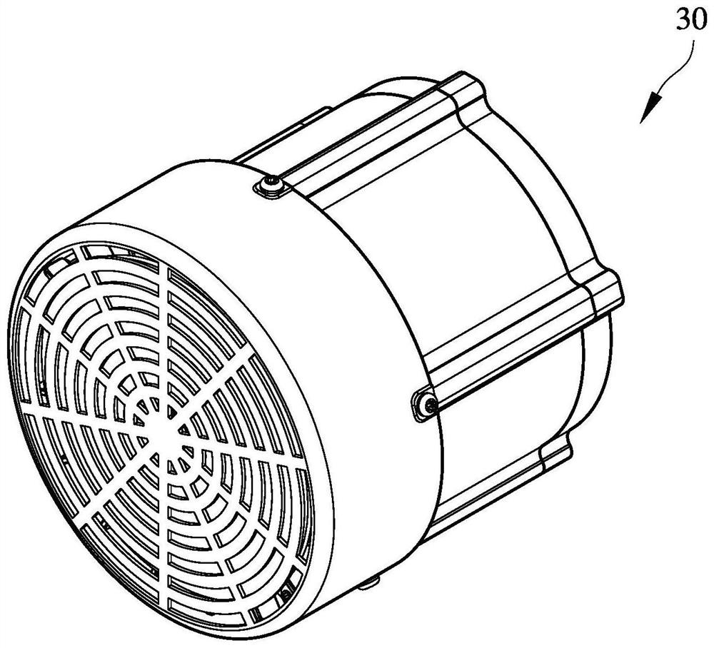
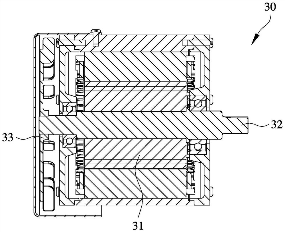
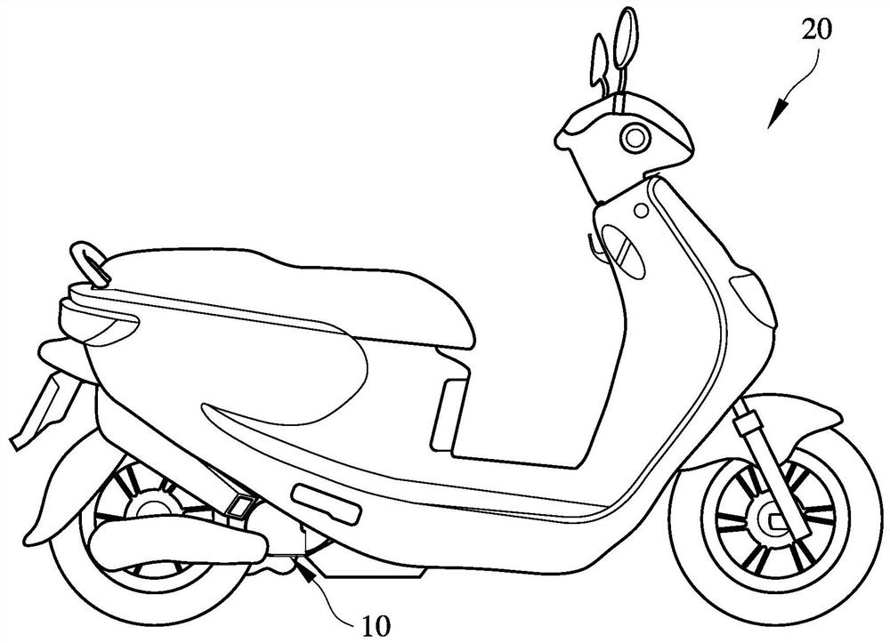
[0021] see Figure 3 to Figure 6 as shown, image 3 is a schematic diagram of a motor device applied to an electric locomotive, Figure 4 It is a perspective view of the motor device and the heat dissipation structure of the motor of the present invention, Figure 5 It is a plane sectional view of the motor device and the heat dissipation structure of the motor of the present invention, Figure 6 It is a three-dimensional exploded view of the motor device and the heat dissipation structure of the motor of the present invention. The present invention relates to a heat dissipation structure of a motor, which is applied to an electric locomotive. A motor device 10 is located on the electric locomotive 20 and is adjacent to the rear wheel of the electric locomotive 20, and includes a motor device 10 located in the middle Yoke 11, one side of the yoke 11 is equipped with a front cover 12, the other side of the yoke 11 corresponding to the front cover 12 is equipped with a rear c...


PUM


Abstract

The invention provides a heat dissipation structure of a motor, which is applied to an electric motor car. A motor device is positioned on the electric motor car and is adjacent to a rear wheel of the electric motor car; the heat dissipation structure comprises a yoke part positioned in the middle of the motor device, a front cover is arranged on one side of the yoke part, and a rear cover is arranged on the other side, corresponding to the front cover, of the yoke part. A plurality of bearings are arranged in the motor device, the motor device is arranged in the front cover and the rear cover, a stator is arranged in the yoke part, a rotor is arranged in the stator, the rotor is provided with a mandrel, and the bearings in the front cover and the rear cover are combined with the mandrel so as to support the rotor; the heat dissipation structure of the motor comprises a fan blade which is arranged on one bearing of the rear cover and located on the other side, corresponding to the yoke part, of the rear cover; and a wind collecting cover which is arranged on the yoke part, wherein the rear cover and the fan blades are accommodated in the wind collecting cover.

Description

technical field [0001] The invention relates to a heat dissipation structure of a motor, in particular to a heat dissipation structure of a motor which enables rapid flow of airflow and rapid cooling of a motor device. Background technique [0002] During the operation of the motor, heat energy is easily accumulated in the motor casing. Since the high temperature generated by the motor operation cannot be eliminated in a timely manner, the heat energy of the motor will cause the magnetic force of the internal magnet to decline, which will cause the operating efficiency of the motor to gradually decrease. When the temperature rises to a certain level, the insulation layer of the stator or rotor coil will be damaged, which will cause a short circuit of the coil and destroy the motor. [0003] Such as Figure 1 to Figure 2 Shown is a perspective view and a plane sectional view of the prior art. A motor device 30 contains a rotor 31 inside, and a spindle 32 is arranged in the r...

Claims


Application Information

Patent Timeline
IPC IPC(8): H02K9/04H02K5/20
CPCH02K5/20H02K9/04
Inventor 林桓槶
Owner SHIHLIN ELECTRIC & ENG CORP
Why Eureka
Try Eureka