


Quick Research
Generate reliable direction feasibility study reports for your R&D in just a few steps.

Technical Q&A
Discover and master advanced knowledge NOW. Basics, ideas, possibilities, all at once.

Find Solutions
As an expert in R&D theories, this can generate solutions to your technical problems instantly.

Evaluate Feasibility
Analyze your overall solution with one click, know your potential R&D risks in advance.

Monitor Landscape
Get weekly tech updates, stay abreast of the latest tech innovations and key insights.
Electric measurement and control device and method suitable for manual valve action test
A manual valve, measurement and control device technology, applied in measuring devices, mechanical valve testing, instruments, etc., can solve the problems of step change in torque, poor versatility, etc., and achieve the effects of low cost, reasonable design and convenient operation
- Summary
- Abstract
- Description
- Claims
- Application Information
AI Technical Summary
Problems solved by technology
Method used
Image


Examples
Embodiment 1
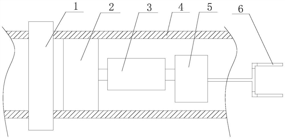
[0052] Such as figure 1 , figure 2 As shown, an electric measurement and control device suitable for manual valve action test, including a housing 4, a control mechanism 1 and a fixture 6;
[0053] The housing 4 is provided with a drive mechanism 2, a stroke detection mechanism 3 and a variable torque control mechanism 5;
[0054] The stroke detection mechanism 3 includes a casing 34, an output torque sensor, a stroke displacement sensor and a locator; the casing 34 is pierced with a dowel 32, and the two ends of the dowel 32 are respectively connected to the drive mechanism 2, the transformer The torque control mechanism 5 is connected;
[0055] The casing 34 is a metal casing, and the two ends of the dowel bar 32 are respectively connected to the two ends of the casing 34 through a conductive support bearing 31 and an insulating support bearing 36. A reset spring 35 is arranged in the casing 34, and the reset The spring 35 is arranged at one end close to the insulating s...
Embodiment 2
[0065] Such as figure 1 , figure 2 As shown, this embodiment is based on Embodiment 1, 3. An electric measurement and control device suitable for manual valve action test according to claim 2, characterized in that, the stroke detection mechanism 3 also includes a contact point 33, so One end of the contact point 33 is connected to the dowel bar 32, and the other end is connected to the housing 34 through a ball head; the contact point 33 is a triangular structure, one side of the triangular structure is connected to the dowel bar 32, and the corresponding vertex is passed through the ball. The head is connected to the shell 34; the stroke displacement sensor is provided with a plurality of stroke displacement sensors forming continuous measurement points on the dowel rod 32; the stroke displacement sensor is installed on the outside of the dowel rod 32 through precision threads.
PUM
 Abstract
Description
Claims
Application Information
 - R&D Engineer
- R&D Manager
- IP Professional
- Industry Leading Data Capabilities
- Powerful AI technology
- Patent DNA Extraction
Browse by: Latest US Patents, China's latest patents, Technical Efficacy Thesaurus, Application Domain, Technology Topic, Popular Technical Reports.
© 2024 PatSnap. All rights reserved.Legal|Privacy policy|Modern Slavery Act Transparency Statement|Sitemap|About US| Contact US: help@patsnap.com