Nail gun
A nail gun and nail feeding technology, which is applied in the field of nail guns, can solve the problems of unstable nail quality, failure to drive to the bottom, overturning, tilting, etc., and achieve the effect of improving the adjustment effect and nail quality
- Summary
- Abstract
- Description
- Claims
- Application Information
AI Technical Summary
Problems solved by technology
Method used
Image


Examples
Embodiment 1
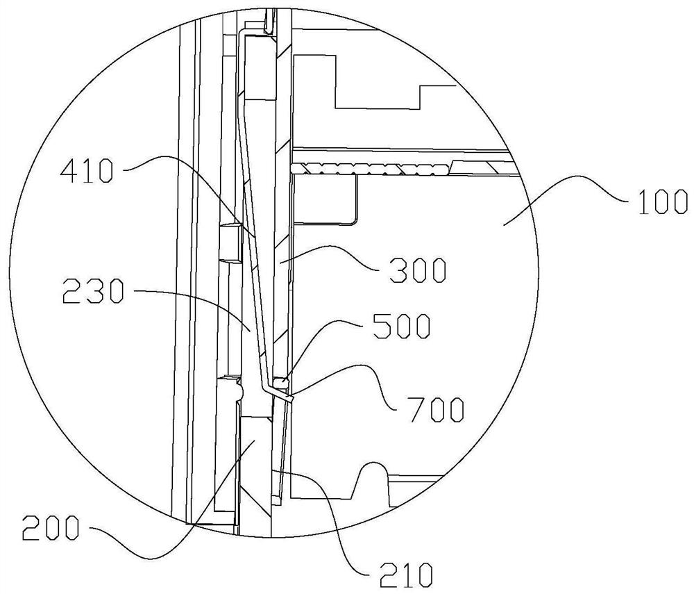
[0038]refer to Figure 1 to Figure 6 As shown, the nail gun in this embodiment includes a housing and a drive mechanism, and the housing is also provided with a nail feeding guide rail 100, a punching guide rail 200, a punching plate 300 and an adjustment member 400, and the punching guide rail 200 and the nail feeding guide rail 100 A nail-out gap 600 for accommodating U nails 500 is formed between the ends, and the drive mechanism is an electric drive mechanism or a pneumatic drive mechanism. These two drive mechanisms have been disclosed in the prior art and will not be described in detail here. The mechanism drives the punching piece 300 to move downward in the nail-out gap 600 to punch out the U nail 500. When nailing, the adjustment member 400 and the punching piece 300 cooperate to adjust the U nail 500 to abut against it in the nail-out gap 600. On the punching guide rail 200, so that the U nail 500 sticks to the punching guide rail 200 for nailing, avoids the U nail 5...
Embodiment 2
[0044] The difference from Embodiment 1 is that the adjustment member in this embodiment includes a fixed arm and a support piece 420 located at the lower end of the fixed arm, the upper end of the fixed arm is hinged on the mounting surface 220, and a There is a return spring, and the support piece 420 runs through the perforation 230. The part of the support piece 420 located in the nail output gap 600 forms an elastic protrusion 700. The support piece 420 is a slanted piece that slopes downward toward the nail feeding guide rail 100, so that the elastic protrusion The top surface of 700 forms a bevel. In this embodiment, under the cooperation of the fixed arm and the return spring, the support piece 420 can be retracted into the perforation 230 or extended into the nail-exiting gap 600, so that the part of the support piece 420 located in the nail-exiting gap can be displaced and formed. Elastic bump 700.
[0045] When nailing, the nail back of the U nail is supported by t...
Embodiment 3
[0048] Compared with Embodiments 1 and 2, the difference of this embodiment is that the elastic projection 700 in this embodiment protrudes into the nail-exiting gap 600 and protrudes from the guide surface 210 at a height smaller than the width of the nail back, so that First, when nailing, one side of the back of the nail can also be hung on the elastic protrusion 700, and the other side can be twisted downward under the impact of its own weight and the punching plate 300 so that the bottom end of the nail foot abuts against the punching plate guide rail 200, and under the impact of the subsequent punch 300, the elastic protrusion 700 retracts into the perforation 230 so that the back of the nail is twisted to lean against the punch guide rail 200. At this time, the top surface of the elastic protrusion does not need to be provided with a slope .
PUM
 Abstract
Description
Claims
Application Information
 - R&D
- Intellectual Property
- Life Sciences
- Materials
- Tech Scout
- Unparalleled Data Quality
- Higher Quality Content
- 60% Fewer Hallucinations
Browse by: Latest US Patents, China's latest patents, Technical Efficacy Thesaurus, Application Domain, Technology Topic, Popular Technical Reports.
© 2025 PatSnap. All rights reserved.Legal|Privacy policy|Modern Slavery Act Transparency Statement|Sitemap|About US| Contact US: help@patsnap.com