
Device and method for measuring thickness and refractive index of thin film

A technology of film thickness and refractive index, which is applied in the field of optical measurement, can solve the problems of difficult film angle, difficult operation, and low measurement accuracy, and achieve the effect of convenient and simple measurement process, high-precision measurement of film thickness, and elimination of disturbance effects

Active Publication Date: 2021-07-27
苏州中科行智智能科技有限公司 +1
View PDF16 Cites 2 Cited by
  • Summary
  • Abstract
  • Description
  • Claims
  • Application Information

AI Technical Summary

Problems solved by technology

Since the Fourier transform is directly used to process the interference signal, the resolution of this method is limited by the Fourier transform resolution (micron level), so the thickness measurement accuracy is low, which in turn leads to low refractive index measurement accuracy;
For samples with unknown refractive index, this measurement method needs to determine the tilt angle of the film sample, which is difficult to operate, especially for soft or easily deformable films, it is very difficult to accurately determine the film angle, and the error is large
[0006]The current non-optical measurement method of film thickness cannot measure the thickness and refractive index of the film at the same time, but there are many optical methods that can measure the thickness and refractive index of the film at the same time Problems, such as high requirements on the state of the film, difficult operation, or low measurement accuracy

Method used


Image

  • Device and method for measuring thickness and refractive index of thin film
  • Device and method for measuring thickness and refractive index of thin film
  • Device and method for measuring thickness and refractive index of thin film

Examples


Embodiment 1

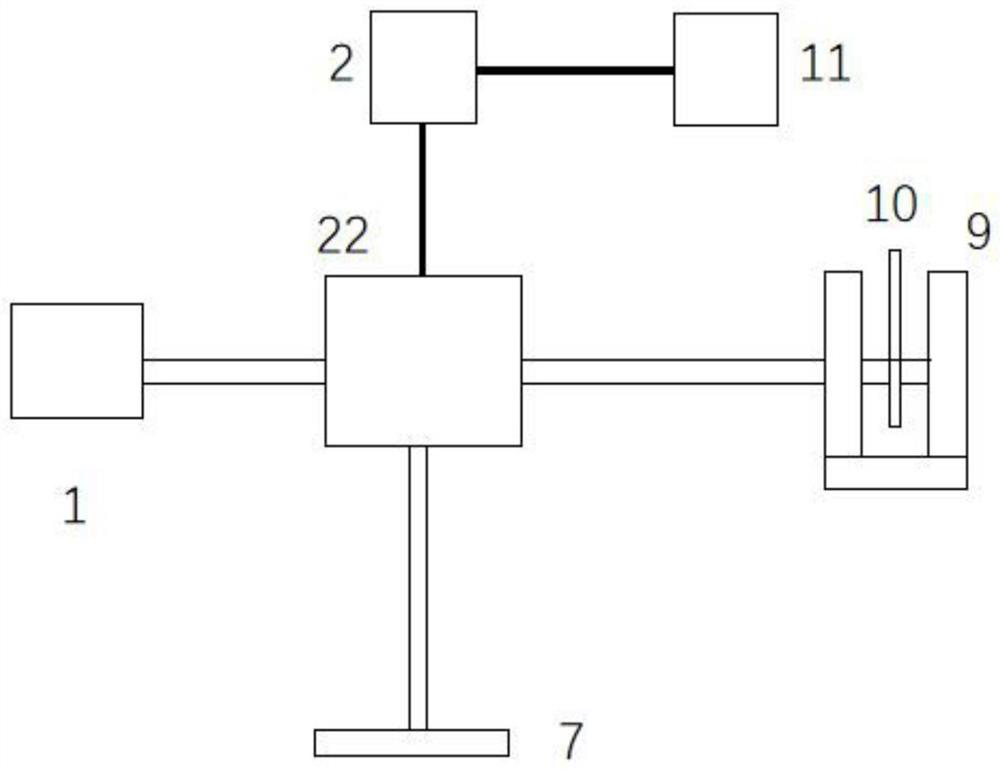
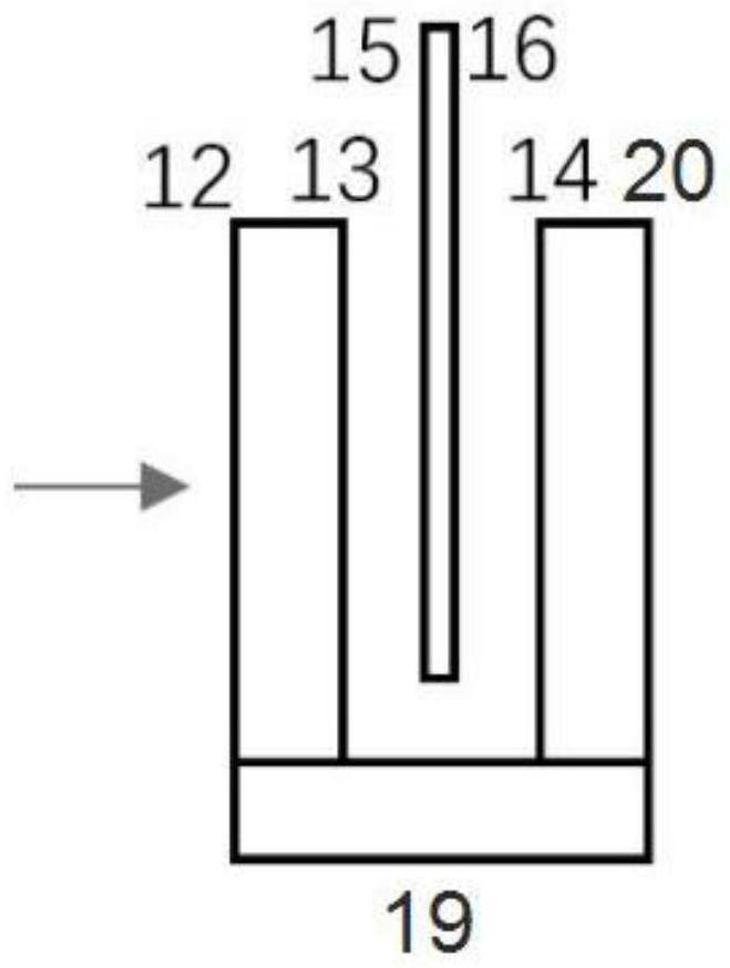
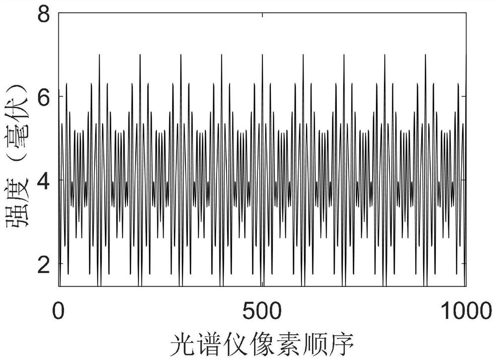
[0148] According to a specific embodiment of the present invention, in combination with the Figure 1-11 , the device and method for measuring the thickness and refractive index of thin films of the present invention will be described in detail. The thickness of the sample used in this embodiment is 10 microns, the coupler is a 2*1 fiber coupler, and the first light splitting element is a beam splitting prism. The method of the present invention identifies the film as a thin film.

[0149] The invention provides a device for measuring film thickness and refractive index, comprising:

[0150] Low coherence light source, 2*1 fiber coupler, collimator, beam splitter prism, first lens, second lens, mirror, sample slot, spectrometer and signal processing unit;

[0151] The low-coherence light source and the spectrometer are connected to a 2*1 fiber coupler through an optical fiber, and the 2*1 optical fiber coupler is connected to a collimator through an optical fiber; the spectro...

Embodiment 2

[0190] According to a specific embodiment of the present invention, in combination with the Figure 1-11 , the method for measuring the thickness and refractive index of a thick film of the present invention is described in detail. The thickness of the sample is 50 microns and the refractive index is 1.2. According to the method of the present invention, the film is determined to be a thick film.

[0191] This embodiment adopts the device for measuring the thickness and refractive index of the film in the first embodiment, and other different embodiments of the device of the present invention can also be used, and the measurement methods are all the same.

[0192] The present invention provides a method for measuring film thickness and refractive index, using the above-mentioned device for measuring film thickness and refractive index, comprising the following steps:

[0193] When there is no sample to be tested in the sample tank 9, when the sample tank 9 is empty, the optica...

Embodiment 3

[0213] According to another specific embodiment of the device of the present invention, the device for measuring the film thickness and the refractive index of the present invention can also be Figure 10 to implement. The first spectroscopic element adopts a spectroscopic prism, and a spectroscopic element that can achieve the same function, such as a spectroscopic sheet, can also be used instead.

[0214] The present invention provides a device for measuring film thickness and refractive index, comprising: a low-coherence light source 1, a spectrometer 2, an optical fiber coupler 3, a reflector 7, a beam splitting prism 5, a sample slot 9, a signal processing unit 11, and a third lens 21; the optical fiber coupler 3 is a 2*1 optical fiber coupler, and other couplers can also be used, at least a 2*1 coupler.

[0215] The low-coherence light source 1 and the spectrometer 2 are connected to the fiber coupler 3 through an optical fiber;

[0216] The spectrometer 2 is electrica...


PUM

PropertyMeasurementUnit
Thicknessaaaaaaaaaa

Abstract

The invention provides a device and a method for measuring the thickness and the refractive index of a thin film, and belongs to the field of optical measurement. The device comprises a low-coherence light source, a light splitting assembly, a reflecting mirror, a sample groove, a spectrograph and a signal processing unit. Light emitted from the low-coherence light source enters the light splitting assembly, and the light is split into reference light and sample light through the light splitting assembly. The reference light irradiates on the reflecting mirror; sample light enters the sample groove perpendicular to the side face of the sample groove. The reference light reflected by the reflecting mirror and the sample light reflected by the sample groove and the sample to be detected are reflected into the light splitting assembly and are output into the spectrograph. The method comprises: demodulating by combining the frequency and phase of Fourier transform, respectively measuring the optical path after the sample groove is vacant and after the sample is placed, and pouring a liquid with known refractive index into the sample groove for measuring the optical path for the thin film. The measuring method based on phase-sensitive optical coherence tomography has the advantages of nanoscale precision, simplicity in operation and applicability to films in various states.

Description

technical field [0001] The invention relates to the technical field of optical measurement, in particular to a device and method for measuring the thickness and refractive index of a thin film. Background technique [0002] The thickness and refractive index of thin films are important parameters that determine their properties. Accurately measuring the refractive index and thickness of thin films is of great significance in the preparation and application of thin films. The current thin film measurement methods are mainly divided into two categories, non-optical methods and optical methods. Non-optical methods can usually only measure the thickness of the thin film, but cannot obtain the refractive index of the thin film. Optical methods have the advantages of high precision and non-contact, and can measure the thickness and refractive index of thin films without destroying the sample. The current optical methods involving film thickness and refractive index include: prism...

Claims


Application Information

Patent Timeline
IPC IPC(8): G01B11/06G01N21/01G01N21/45
CPCG01B11/06G01B11/0675G01N21/01G01N21/45
Inventor 王一洁彭思龙汪雪林顾庆毅赵效楠王毅周越焦智成
Owner 苏州中科行智智能科技有限公司
Learn More