
Light-emitting diode lamp and using method thereof

A technology of light-emitting diodes and lamps, which is applied in the direction of cleaning methods using tools, cleaning methods and utensils, chemical instruments and methods, etc., which can solve problems such as single functions, and achieve the effects of improving performance, lighting range, and service life

Inactive Publication Date: 2021-07-27
深圳市正东明光电子有限公司
View PDF6 Cites 2 Cited by
  • Summary
  • Abstract
  • Description
  • Claims
  • Application Information

AI Technical Summary

Problems solved by technology

[0005] To this end, the present invention provides a light-emitting diode lamp and its use method. The heat dissipation device is operated through the driving device to achieve heat dissipation for the LED lamp, and the driving device is used to drive the swing device to work through the transmission device, thereby achieving Swing the LED lamp, and then drive the driving device to drive the cleaning device to work through the transmission device 2, so as to clean the dust on the shell, so as to solve the problem of the single function of the existing light-emitting diode lamps

Method used


Image

  • Light-emitting diode lamp and using method thereof
  • Light-emitting diode lamp and using method thereof
  • Light-emitting diode lamp and using method thereof

Examples


Embodiment Construction

[0044] The preferred embodiments of the present invention will be described below in conjunction with the accompanying drawings. It should be understood that the preferred embodiments described here are only used to illustrate and explain the present invention, and are not intended to limit the present invention.

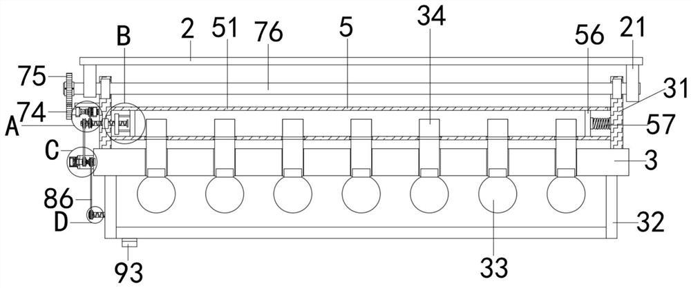
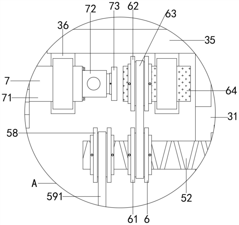
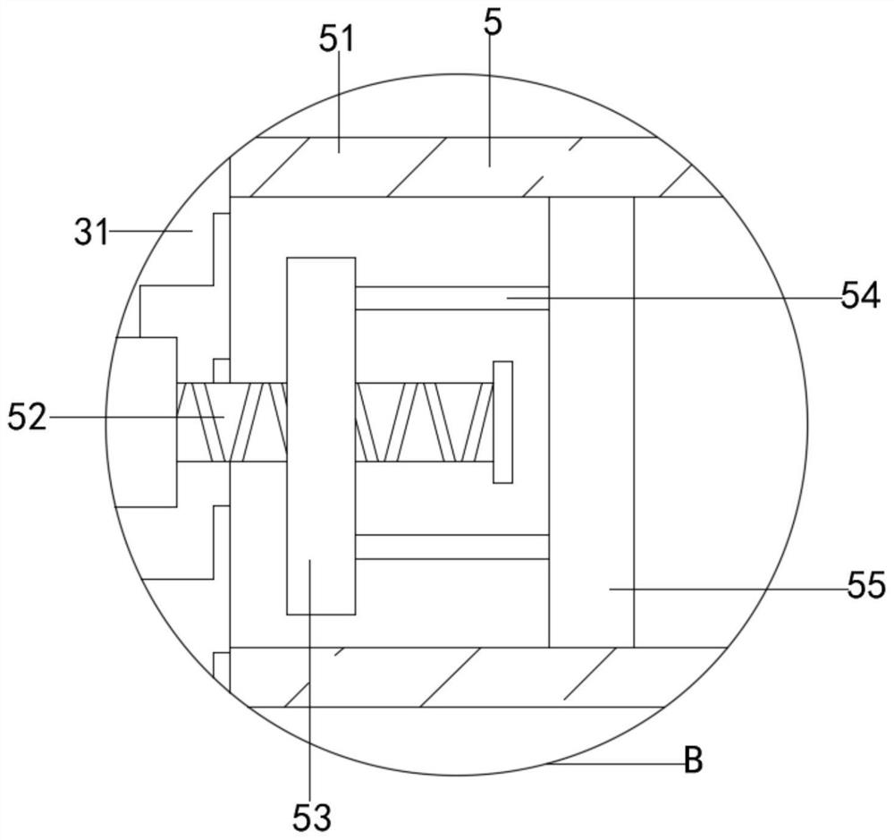
[0045] Refer to attached Figure 1-Figure 9 , a light-emitting diode lamp provided by the present invention comprises a top plate 2 and a bottom plate 3, a connecting plate 21 is fixedly installed at both ends of the bottom of the top plate 2, a square plate 31 is fixedly installed at both ends of the top of the bottom plate 3, and the bottom of the bottom plate 3 The housing 32 is fixedly installed, the outer wall on the left side of the square plate 31 is fixedly installed with a support plate 35, and the two ends of the bottom of the support plate 35 are fixedly installed with a connecting plate 2 36, and also includes: a driving device 4 installed on the left sid...


PUM


Abstract

The invention discloses a light-emitting diode lamp and a using method thereof, and particularly relates to the technical field of light-emitting diodes. The technical scheme is that the light-emitting diode lamp comprises a top plate and a bottom plate, first connecting plates are fixedly installed at the two ends of the bottom of the top plate, square plates are fixedly installed at the two ends of the top of the bottom plate, and a shell is fixedly installed at the bottom of the bottom plate; a supporting plate is fixedly installed on the outer wall of the left side of each square plate, and second connecting plates are fixedly installed at the two ends of the bottom of the supporting plate; and the light-emitting diode lamp also includes a driving device installed on the left side of the bottom plate, a heat dissipation device connected to the inner wall of each square plate, a swinging device connected to the top end of each square plate, a first transmission device connected between the swinging device and the heat dissipation device, and a cleaning device connected to the bottom end of the shell. The light-emitting diode lamp has the beneficial effects that the light-emitting diode lamp has the multiple functions of heat dissipation, swinging and cleaning, the use range of the light-emitting diode lamp can be widened, the market competition of the light-emitting diode lamp can be improved, and the cost investment can be reduced.

Description

technical field [0001] The invention relates to the field of light-emitting diodes, in particular to a light-emitting diode lamp and a use method thereof. Background technique [0002] Light-emitting diodes, referred to as LEDs for short, are made of compounds containing gallium (Ga), arsenic (As), phosphorus (P), nitrogen (N), etc. When electrons and holes recombine, they can radiate visible light, so they can be used to make Light-emitting diodes are used as indicator lights in circuits and instruments, or to form text or digital displays. Gallium arsenide diodes emit red light, gallium phosphide diodes emit green light, silicon carbide diodes emit yellow light, and gallium nitride diodes emit blue light. Due to chemical properties, it can be divided into organic light-emitting diode OLED and inorganic light-emitting diode LED. Light-emitting diode is a commonly used light-emitting device, which releases energy and emits light through the recombination of electrons and hol...

Claims


Application Information

Patent Timeline
Patent Type & Authority Applications(China)
IPC IPC(8): F21S8/04F21V29/56F21V21/15F21V33/00F21V29/71F21V19/00B08B1/00F21Y115/10
CPCF21S8/04F21V29/56F21V21/15F21V33/00F21V29/717F21V19/001F21Y2115/10B08B1/143
Inventor 赵维
Owner 深圳市正东明光电子有限公司
Learn More