Recovery device for waste heat of tail gas from chemical device

A technology of waste heat recovery device and absorption device, which is applied in the directions of transportation and packaging, chemical instruments and methods, separation methods, etc., which can solve the problems of troublesome cleaning, equipment blockage and damage, and dust easy to block filter equipment, etc., and achieve the effect of convenient use

Inactive Publication Date: 2021-07-27
苏金泉
View PDF7 Cites 0 Cited by
  • Summary
  • Abstract
  • Description
  • Claims
  • Application Information

AI Technical Summary

Problems solved by technology

However, when the existing chemical equipment recovers the waste heat of the waste gas, the dust in the waste gas also enters the equipment. Although some waste heat recovery equipment has the function of filtering and can separate the dust in the waste gas, the dust accumulates Inside, it is troublesome to clean up; and the equipment is in continuous operation for a long time, and the dust is easy to block the filter equipment, causing the equipment to be blocked and damaged

Method used


Image

  • Recovery device for waste heat of tail gas from chemical device
  • Recovery device for waste heat of tail gas from chemical device
  • Recovery device for waste heat of tail gas from chemical device

Examples


Embodiment Construction

[0029] The following will clearly and completely describe the technical solutions in the embodiments of the present invention with reference to the accompanying drawings in the embodiments of the present invention. Obviously, the described embodiments are only some, not all, embodiments of the present invention. Based on the embodiments of the present invention, all other embodiments obtained by persons of ordinary skill in the art without making creative efforts belong to the protection scope of the present invention.

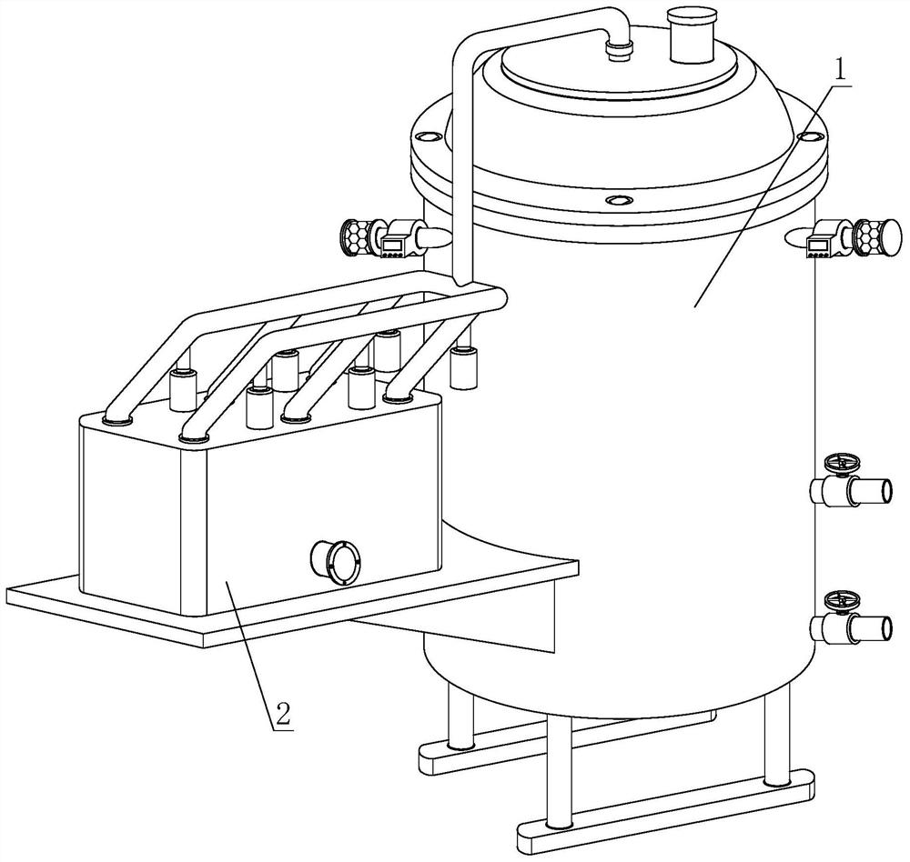
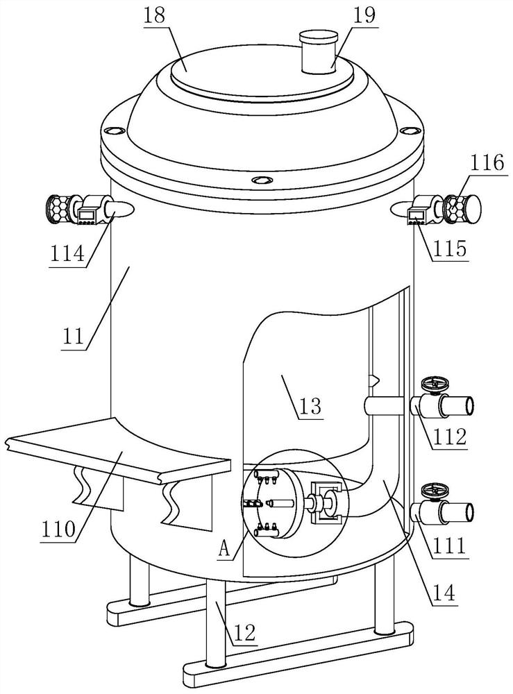
[0030] see Figure 1-4 , a tail gas waste heat recovery device of a chemical plant, comprising a waste heat absorption device 1 and a dust removal device 2, the dust removal device 2 is installed on the outer wall of one side of the waste heat absorption device 1, and the waste heat absorption device 1 includes an outer cylinder 11, a base 12, an inner cylinder 13. Air guide pipe 14, connecting rod 15, fixed collar 16, air injection assembly 17, top cover 18 a...


PUM


Abstract

The invention discloses a recovery device for waste heat of tail gas from a chemical device. The recovery device comprises a waste heat absorption device and a dust removal device, wherein a slow flow box is arranged on the side wall of an outer cylinder through a supporting frame; an S-shaped drainage plate is utilized in the slow flow box to form a curved gas channel between a partition plate and the inner wall of the slow flow box; a strip-shaped hole is formed in the partition plate to communicate with a flow dividing pipe at the top of the slow flow box; the flow dividing pipe communicates with a top cover of the outer cylinder through a U-shaped pipe and a connecting pipe; an ash receiving tank is vertically arranged on the side wall of a top port of the flow dividing pipe through an ash discharging pipe; the flow dividing pipe and the ash discharging pipe are arranged in a herringbone mode; a filter screen is arranged at the connecting port of the flow dividing pipe and the U-shaped pipe; and a baffle is arranged on the inner wall of the flow dividing pipe on the side, away from the U-shaped pipe, of the end port of the ash discharging pipe. According to the invention, hot waste gas mixed with dust enters the slow flow box from the gas inlet pipe, is retarded by the curved gas channel, then enters the flow dividing pipe to undergo flow dividing and speed reducing again and flows to the end port of the flow dividing pipe for filtration by the filter screen, then dust falls into the dust receiving tank under the cooperation of gravity and the baffle, and thus, automatic separation and discharging of the waste gas and the dust are achieved.

Description

technical field [0001] The invention relates to the technical field of environmental protection equipment, in particular to a tail gas waste heat recovery device of a chemical plant. Background technique [0002] Industrial waste gas refers to the general term for all kinds of pollutant gases that are discharged into the air during fuel combustion and production processes in the factory area. These exhaust gases include: carbon dioxide, carbon disulfide, hydrogen sulfide, fluoride, nitrogen oxides, chlorine, hydrogen chloride, carbon monoxide, sulfuric acid (mist) lead mercury, beryllium compounds, smoke and productive dust, which will pollute the air when discharged into the atmosphere. These substances enter the human body through the respiratory tract in different ways, some directly cause harm, and some have a cumulative effect, which will seriously endanger human health. Different substances will have different effects. [0003] When industrial waste gas is produced, ...

Claims


Application Information

Patent Timeline
IPC IPC(8): B01D46/10B01D46/00B01D46/48B01D53/78
CPCB01D46/10B01D46/0041B01D46/48B01D53/78B01D46/76
Inventor 苏金泉
Owner 苏金泉
Why Eureka
Try Eureka