


Quick Research
Generate reliable direction feasibility study reports for your R&D in just a few steps.

Technical Q&A
Discover and master advanced knowledge NOW. Basics, ideas, possibilities, all at once.

Find Solutions
As an expert in R&D theories, this can generate solutions to your technical problems instantly.

Evaluate Feasibility
Analyze your overall solution with one click, know your potential R&D risks in advance.

Monitor Landscape
Get weekly tech updates, stay abreast of the latest tech innovations and key insights.
Frameless display switch device
A display switch, borderless technology, applied to the display field, can solve the problems of easy glare on the peripheral edge of the lens, affecting the display effect, small viewing angle of the screen, etc.
- Summary
- Abstract
- Description
- Claims
- Application Information
AI Technical Summary
Problems solved by technology
Method used
Image

Examples
Embodiment 1
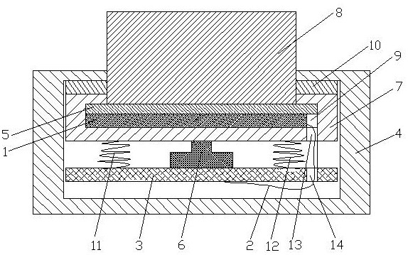
[0036] see figure 1 , a frameless display switching device, including a display panel 1, a display drive lead 2 and a printed circuit board 3, the display panel 1 is electrically connected to the printed circuit board 3 through the display drive lead 2, and also includes a fixed shell 4, optical glue 5, A key switch 6, a display case 7 and an optical fiber panel 8 for conducting light, the printed circuit board 3, the key switch 6, the display case 7 and the display panel 1 are arranged in the fixed case 4, and the key switch 6 is arranged on the display Between the shell 7 and the printed circuit board 3, the top of the key switch 6 is connected to the display shell 7, and the bottom of the key switch 6 is connected to the printed circuit board 3, and the display shell 7 is fixed on the inner top wall of the fixed shell 4 to display There is a groove 9 inside the casing 7, the display panel 1 is fixed in the groove 9, the cross section of the groove 9 is inverted "T" shape, a...
Embodiment 2
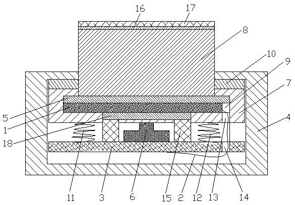
[0039] see figure 1 , a frameless display switching device, including a display panel 1, a display drive lead 2 and a printed circuit board 3, the display panel 1 is electrically connected to the printed circuit board 3 through the display drive lead 2, and also includes a fixed shell 4, optical glue 5, A key switch 6, a display case 7 and an optical fiber panel 8 for conducting light, the printed circuit board 3, the key switch 6, the display case 7 and the display panel 1 are arranged in the fixed case 4, and the key switch 6 is arranged on the display Between the shell 7 and the printed circuit board 3, the top of the key switch 6 is connected to the display shell 7, and the bottom of the key switch 6 is connected to the printed circuit board 3, and the display shell 7 is fixed on the inner top wall of the fixed shell 4 to display There is a groove 9 inside the casing 7, the display panel 1 is fixed in the groove 9, the cross section of the groove 9 is inverted "T" shape, a...
Embodiment 3
[0043] see figure 1 , a frameless display switching device, including a display panel 1, a display drive lead 2 and a printed circuit board 3, the display panel 1 is electrically connected to the printed circuit board 3 through the display drive lead 2, and also includes a fixed shell 4, optical glue 5, A key switch 6, a display case 7 and an optical fiber panel 8 for conducting light, the printed circuit board 3, the key switch 6, the display case 7 and the display panel 1 are arranged in the fixed case 4, and the key switch 6 is arranged on the display Between the shell 7 and the printed circuit board 3, the top of the key switch 6 is connected to the display shell 7, and the bottom of the key switch 6 is connected to the printed circuit board 3, and the display shell 7 is fixed on the inner top wall of the fixed shell 4 to display There is a groove 9 inside the casing 7, the display panel 1 is fixed in the groove 9, the cross section of the groove 9 is inverted "T" shape, a...
PUM
 Abstract
Description
Claims
Application Information
 - R&D Engineer
- R&D Manager
- IP Professional
- Industry Leading Data Capabilities
- Powerful AI technology
- Patent DNA Extraction
Browse by: Latest US Patents, China's latest patents, Technical Efficacy Thesaurus, Application Domain, Technology Topic, Popular Technical Reports.
© 2024 PatSnap. All rights reserved.Legal|Privacy policy|Modern Slavery Act Transparency Statement|Sitemap|About US| Contact US: help@patsnap.com