Drying device for tea leaves
A technology for drying equipment and tea leaves, which is applied in drying, drying machines, lighting and heating equipment, etc., which can solve the problems of inconvenient automatic impurity removal and single function, and achieve improved winnowing quality, good drying effect, and uniform drying effect
- Summary
- Abstract
- Description
- Claims
- Application Information
AI Technical Summary
Problems solved by technology
Method used
Image
Examples
Embodiment 1
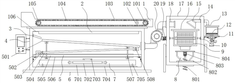
[0035] Example 1: see Figure 1-6 , a tea drying equipment, comprising a base 4 and a base 6, the bottom end of the base 4 is provided with a base 6, the top of the base 4 is provided with a heating plate 2, and the model of the heating plate 2 can be JQ-024, The top of the heating plate 2 is provided with a conveying mechanism 1, one side of the top of the base 4 is provided with a guide plate 3, the middle position inside the base 4 is provided with a vibrating screen mechanism 5, and the bottom end of the base 4 is provided with a collection mechanism 7. A casing 17 is arranged on the other side of the base 4, and a duct fan 20 is arranged between the casing 17 and the base 4. The model of the duct fan 20 can be HCC-30S, the output end and the input end of the duct fan 20 A material extraction pipe 18 is respectively provided, the casing 17 is communicated with the interior of the base 4 through the material extraction pipe 18, the bottom end inside the casing 17 is provide...
Embodiment 2
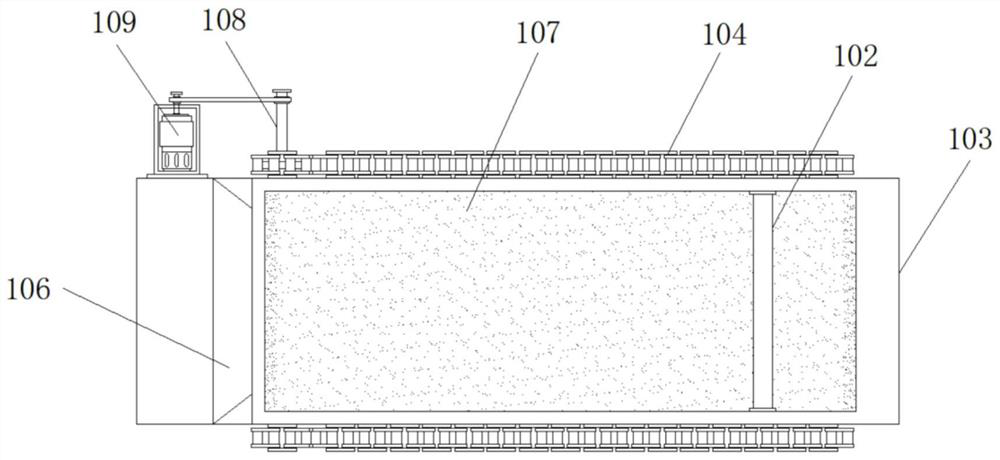
[0039] Embodiment 2: The transmission mechanism 1 is composed of a driven gear 101, a blocking rod 102, a drying table 103, a chain 104, a driving gear 105, a blanking chute 106, a conveyor belt 107, a transmission shaft 108 and a reduction motor 109. The drying table 103 Set on the top of the base 4, the drying table 103 is provided with a conveyor belt 107, one side of the conveyor belt 107 is provided with a driving gear 105, the other side of the conveyor belt 107 is provided with a driven gear 101, and the other side of the driving gear 105 is provided. One end is fixedly connected with a transmission shaft 108, and the other end of one side of the drying table 103 is fixedly connected with a deceleration motor 109. The model of the deceleration motor 109 can be 2IK6GN-C, and the output end of the deceleration motor 109 is fixedly connected with the transmission shaft 108 through a transmission belt. , a chain 104 is engaged with the outside of the driving gear 105 and the...
Embodiment 3
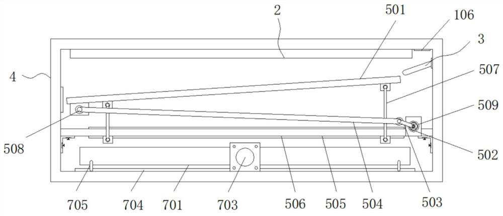
[0042] Embodiment 3: The vibrating screen mechanism 5 is composed of a screen plate 501, a first rotating shaft 502, a turning handle 503, a transmission rod 504, a fixing plate 505, a through groove 506, a hinge rod 507 and a second rotating shaft 508, and the fixing plate 505 is fixedly connected to the Inside the base 4, the inside of the fixed plate 505 is provided with a through groove 506, the two sides of the two ends of the fixed plate 505 are respectively hinged with hinge rods 507, the top of the hinge rod 507 is hinged with a sieve plate 501, and one side of the fixed plate 505 is movably connected There is a first rotating shaft 502, one end of the first rotating shaft 502 is fixedly connected with a turning handle 503, one end of the turning handle 503 is fixedly connected with a transmission rod 504, and the bottom end of the other side of the screen plate 501 is movably connected with a second rotating shaft 508, the second One end of the rotating shaft 508 is ar...
PUM
 Abstract
Description
Claims
Application Information
 - R&D Engineer
- R&D Manager
- IP Professional
- Industry Leading Data Capabilities
- Powerful AI technology
- Patent DNA Extraction
Browse by: Latest US Patents, China's latest patents, Technical Efficacy Thesaurus, Application Domain, Technology Topic, Popular Technical Reports.
© 2024 PatSnap. All rights reserved.Legal|Privacy policy|Modern Slavery Act Transparency Statement|Sitemap|About US| Contact US: help@patsnap.com


