Speed regulatable and tightenable express transfer assembly line and application method

An assembly line and speed regulation technology, applied in the direction of conveyors, conveyor objects, conveyor control devices, etc.

Active Publication Date: 2021-07-23
上海申雪供应链管理有限公司
View PDF6 Cites 0 Cited by
  • Summary
  • Abstract
  • Description
  • Claims
  • Application Information

AI Technical Summary

Problems solved by technology

[0003] The technical problem to be solved by the present invention is to overcome the defects of the prior art. The present invention provides a speed-adjustable and tightenable express transmission line. Tighten the internal machinery of the express transmission line to provide current, so that the entire assembly line starts to run, and then press the fifth button to make the four telescopic blocks start to shrink, and the four telescopic blocks can move the first conveyor belt and the second conveyor belt on the one hand. Tighten, so that the first conveyor belt and the second conveyor belt can perform express delivery, on the other hand, the first conveyor belt and the second conveyor belt can be relaxed, so that the first conveyor belt and the second conveyor belt can stop express delivery, and because the rollers cannot move The conveyor belt is tightened so that the conveyor belt will not continue to run due to the effect of inertia, thereby avoiding the occurrence of damage to the express delivery caused by the drop of the express delivery that cannot be collected in time due to too many express deliveries, and the contraction operation of the four telescopic blocks will drive The first roller, the third roller, the fourth roller and the sixth roller do the extended movement, and the first conveyor belt and the second conveyor belt will be tightened as the first roller, the third roller, the fourth roller and the sixth roller do the extended movement, And the six rollers play the role of supporting and tensioning the first conveyor belt and the second conveyor belt on the one hand, and on the other hand, play the role of speeding up the first conveyor belt and the second conveyor belt, while the first roller and the fourth roller expand The movement will drive the two-way gears in the first drive mechanism and the third drive mechanism to move around; when the two-way gears move around, the speed belt will be closely attached to the second speed belt connection block, and the second speed belt connection block will be lifted. The effect of speed-up is reached. At this time, press the first button and the third button to start the motors in the first drive mechanism and the third drive mechanism. With the operation of the motor, the rotation of the rotating shaft will be driven, and the rotation of the rotating shaft will It will drive the rotation of the one-way gear, and the rotation of the one-way gear will drive the rotation of the speed belt. At the same time, the rotation of the speed belt will drive the rotation of the two-way gear, so that the rotation of the two-way gear will drive the rotation of the first roller and the fourth roller. And the rotation of the first roller and the fourth roller can make the first conveyor belt and the second conveyor belt start running, so as to carry out the operation of express delivery; when the rotation of the first roller and the fourth roller will drive the rotation of the first conveyor belt and the second conveyor belt , the rotation of the first conveyor belt and the second conveyor belt will drive the rotation of the third roller and the sixth roller, and the rotation of the third roller and the sixth roller will drive twelve first sliding wheels and twelve first sliding wheels The two sliding wheels start to rotate, and the twelve sliding wheels and the twelve second sliding wheels play the role of supporting the first conveyor belt and the second conveyor belt on the one hand, and can protect the first conveyor belt and the second conveyor belt on the other hand. At the same time, the transmission speed of the first conveyor belt and the second conveyor belt can be accelerated on a certain basis. At this point, the entire assembly line starts to run normally. At this time, the objects to be transmitted are placed on the surface of the first conveyor belt and the second conveyor belt. When the object to be conveyed is placed on the surface of the first conveyor belt and the second conveyor belt, the object will move forward with the rotation of the first conveyor belt and the second conveyor belt, and at the same time, the object It will be collected through the first receiving chute and the second receiving chute placed at the groove in the first concave baffle and the second concave baffle, and the first concave baffle and the second concave baffle protect the The role of the first conveyor belt and the second conveyor belt, on the other hand, can also allow the conveyed express to be transported from the grooves in the first concave baffle and the second concave baffle to the first receiving trough and the second receiving in an orderly manner. At the same time, if you feel that the speed of the objects conveyed by the first conveyor belt and the second conveyor belt is not fast enough, you can also press the second button and the fourth button; when the second button and the fourth button are pressed, the second drive mechanism will and the motor in the fourth driving mechanism starts to run, and along with the operation of the second driving mechanism and the fourth driving mechanism, the operation of the second roller and the fifth roller will be driven, and the operation of the second roller and the fifth roller will give the first The conveyor belt and the second conveyor belt provide thrust, so that the speed of the first conveyor belt and the second conveyor belt to convey the object is accelerated. When the express delivery to be conveyed is completed, press the switch button and then cut off the power supply, so far the operation is completed, and the second drive mechanism and the design of the fourth drive mechanism can provide thrust to the first conveyor belt and the second conveyor belt, thereby allowing the original speed of the first conveyor belt and the second conveyor belt to be promoted to a higher level; among the present invention, the first drive mechanism, the second drive mechanism, The design of the third driving mechanism, the fourth driving mechanism, the first conveyor belt, the second conveyor belt, the first sliding wheel, the second sliding wheel, six rollers, six fixing mechanisms and four telescopic blocks can adjust the first conveyor belt and The speed of the second conveyor belt, so that the transmission speed of the first conveyor belt and the second conveyor belt can be increased or lowered, which saves the time of express delivery to a certain extent, and the design of the four telescopic blocks can tighten or loosen the first conveyor belt. One conveyor belt and the second conveyor belt, and when tensioned, the first conveyor belt and the second conveyor belt can be used to deliver the express delivery, and when the first conveyor belt and the second conveyor belt are relaxed, the first conveyor belt and the second conveyor belt can stop delivering the express delivery, thereby avoiding the failure to collect the express delivery in time due to too many deliveries The occurrence of damage to the express delivery caused by the drop of the express delivery solves the problem mentioned in the above background technology. Nowadays, the current assembly line uses a uniform speed for express delivery. To a certain extent, it is time-consuming. At the same time, if there are too many items on the assembly line, it is necessary to temporarily stop the express delivery. However, the current assembly line can only turn off the power at the same time to stop the entire assembly line from working. Although the assembly line stops working, the effect of inertia It will also let the conveyor belt on the assembly line continue to run for a period of time, so that the courier on the conveyor belt will continue to move forward due to the operation of the conveyor belt, and because there are too many couriers, the courier cannot be collected in time, which will cause the courier to fall and cause the courier to fall. The problem of the occurrence of the damage

Method used


Image

  • Speed regulatable and tightenable express transfer assembly line and application method
  • Speed regulatable and tightenable express transfer assembly line and application method
  • Speed regulatable and tightenable express transfer assembly line and application method

Examples


Embodiment 1

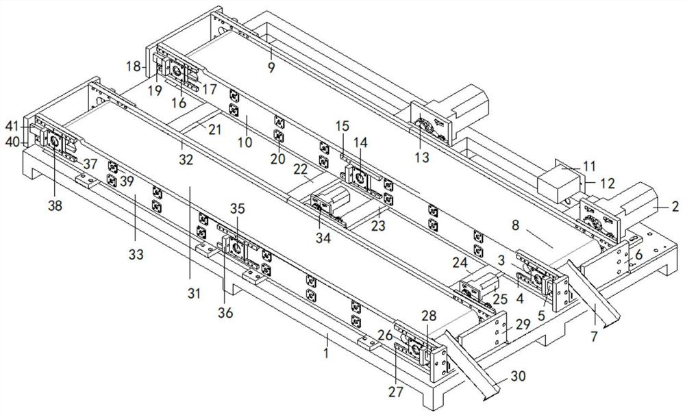
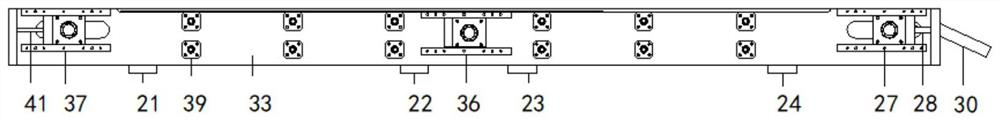
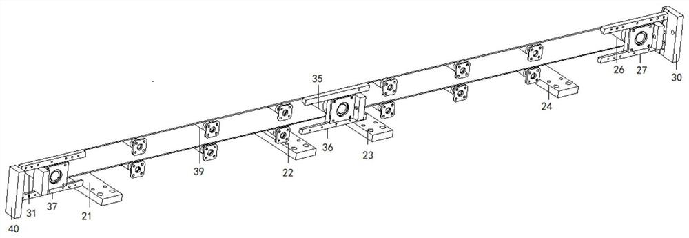
[0038] Such as Figure 1-9 As shown, the speed-adjustable and tightenable express transmission line includes a base 1, the other side of the upper end of the base 1 is connected with a first driving mechanism 2, one side of the first driving mechanism 2 is connected with a first roller 3, and the first One side of the roller 3 is connected with a first fixing mechanism 4, and the first fixing mechanism 4 plays a fixed role, one side of the first fixing mechanism 4 is connected with a first telescopic block 5, and one side of the first telescopic block 5 is connected There is a first concave baffle 6, one end of the first concave baffle 6 is connected with a first receiving chute 7, and the first receiving chute 7 plays a role of collecting express delivery, and the other end of the first concave baffle 6 is connected to There is a first conveyor belt 8, a first baffle plate 9 is installed on one side of the first conveyor belt 8, and the first conveyor belt 8 plays the role of...

Embodiment 2

[0048] The method of using the speed-adjustable and tightenable express delivery line is as follows:

[0049] Step 1: After turning on the power, press the switch button 1204, so that the power box 11 can provide current to the internal machinery of the adjustable speed and tightenable express transmission line, so that the entire assembly line starts to run, and then press the fifth button 1206 Make the four telescopic blocks start to shrink, and the first roller 3, the third roller 17, the fourth roller 26 and the sixth roller 38 will be driven to expand along with the four telescopic blocks 1206. Roller 3, the third roller 17, the fourth roller 26 and the sixth roller 38 do the expansion movement to tighten the first conveyor belt 8 and the second conveyor belt 31, and at the same time the expansion movement of the first roller 3 and the fourth roller 26 will drive the first drive The two-way gear 2005 in the mechanism 2 and the third driving mechanism 25 moves around;

[...

Embodiment 3

[0055] After turning on the power, press the switch button 1204, so that the power supply box 11 can provide current to the internal machinery of the adjustable speed and tightenable express transmission line, so that the entire assembly line can start running, and then press the fifth button 1206 to make the four The telescopic block starts to shrink, and the first roller 3, the third roller 17, the fourth roller 26 and the sixth roller 38 will be driven to expand along with the four telescopic blocks. The tension of the first conveyor belt 8 and the second conveyor belt 31, along with the first roller 3, the third roller 17, the fourth roller 26 and the sixth roller 38, will make the first conveyor belt 8 and the second conveyor belt 31 tense At the same time, the expansion movement of the first roller 3 and the fourth roller 26 will drive the two-way gear 2005 in the first drive mechanism 2 and the third drive mechanism 25 to move around, and the first drive mechanism 2 and ...


PUM


Abstract

The invention discloses a speed regulatable and tightenable express transfer assembly line which comprises a base, wherein the other side of the upper end of the base is connected with a first driving mechanism, one side of the first driving mechanism is connected with a first roller, one side of the first roller is connected with a first fixing mechanism, one side of the first fixing mechanism is connected with a first telescopic block, one side of the first telescopic block is connected with a first concave baffle plate, one end of the first concave baffle plate is connected with a first receiving groove and the other end of the first concave baffle plate is connected with a first conveyor belt. By designing the first driving mechanism, the second driving mechanism, a third driving mechanism, a fourth driving mechanism, the first conveyor belt, a second conveyor belt, a first sliding wheel, a second sliding wheel, six rollers, six fixing mechanisms and four telescopic blocks, the speeds of the first conveyor belt and the second conveyor belt can be regulated, such that the conveying speeds of the first conveyor belt and the second conveyor belt can be improved or the speeds are reduced, and therefore, the express transfer time is saved to a certain extent.

Description

technical field [0001] The invention relates to the field of assembly lines, in particular to an adjustable-speed and tightenable express delivery pipeline, and more particularly to an adjustable-speed and tightenable express delivery pipeline and a method of use. Background technique [0002] Today's assembly lines use uniform speed for express delivery, so express delivery at a constant speed is time-consuming to a certain extent. At the same time, if there are too many items on the assembly line, the express delivery needs to be temporarily stopped. But the current assembly line can only turn off the power at the same time to stop the entire assembly line from working. Although the assembly line stops working, the conveyor belt on the assembly line will continue to run for a period of time under the action of inertia, so that there will be express delivery on the conveyor belt because of the conveyor belt. The operation continues to move forward, and because there are too...

Claims


Application Information

Patent Timeline
IPC IPC(8): B65G23/44B65G15/30B65G23/24B65G39/12B65G43/00
CPCB65G23/44B65G15/30B65G23/24B65G39/12B65G43/00
Inventor 马青青
Owner 上海申雪供应链管理有限公司
Why Eureka
Try Eureka